FBEI GG1
1"- Configuration
- In-line flanges (Fig. 11)
- Approximate weight
- 9 kg


Internal gear pumps for viscous-fluid transfer. Compare models and connections, and assess sealing, drive and heating options for your process.

Explore the catalog sizes and dimensional records from the manual. Share your process conditions to select the equipment.
Compare series limits and sizes. Equipment selection starts with your process conditions.
These are independent series maxima, not a simultaneous duty point or ratings for every model. Flow, pressure, viscosity and temperature must be assessed together by the technical team.
The 340 °C temperature does not change the MAN001-10 heating jacket limits: steam up to 185 °C and thermal fluid up to 232 °C, both up to 10 bar.
up to 6.8 m³/h
up to 23 m³/h
up to 32 m³/h
up to 45 m³/h
up to 70 m³/h
up to 136 m³/h
Flow values are the published maxima for each size. Your process flow depends on the operating conditions and selected configuration. N · 6″: ask our technical team for dimensions, weight and performance curve.
FBEI · Limits and sizes (Portuguese PDF, p. 4, 16.1 MB)The MAN001-10 manual covers 10 models and configurations from 1″ to 4″. Select a size or code to review the installation data.
Selection shows the chosen size and the immediately smaller and larger sizes, when available.
10 models in the manual
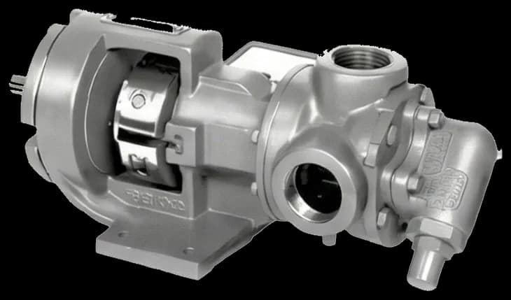
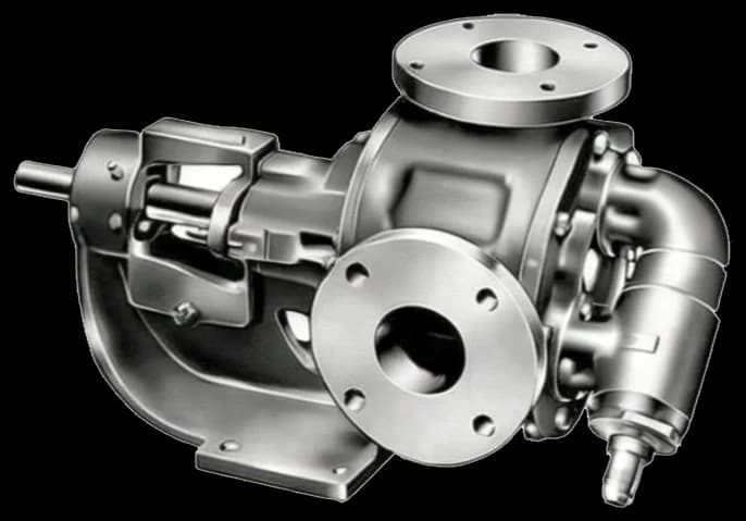
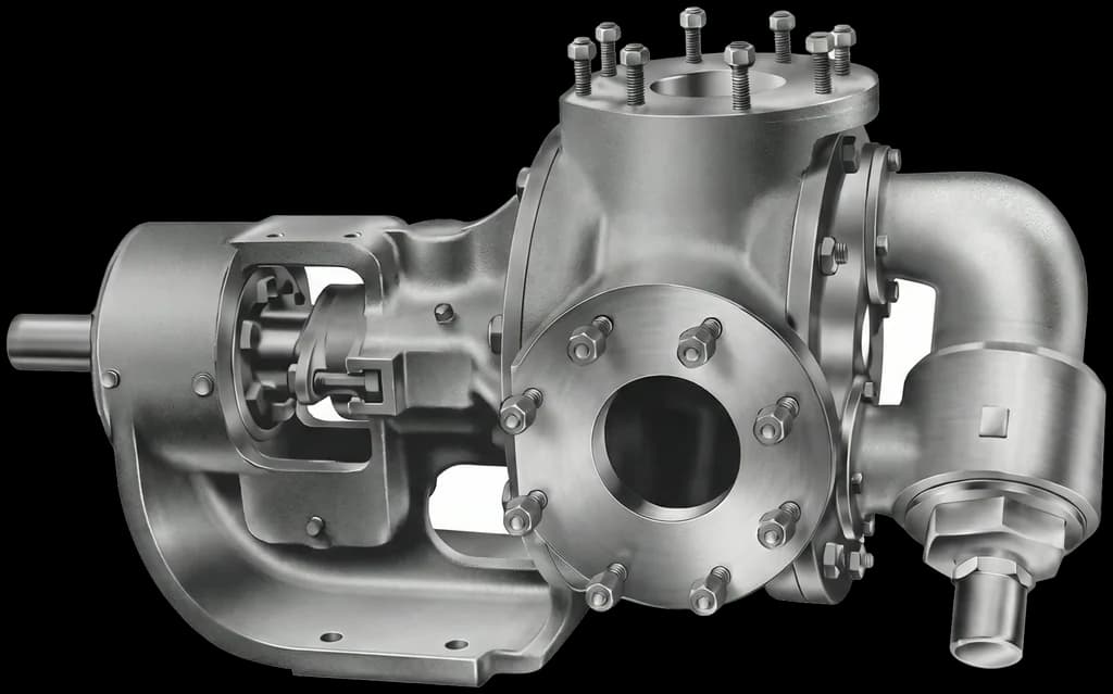
Configuration, sealing and heating need to match the conditions of your process.
Follow the internal gear principle through four stages of the same cycle.
Liquid enters the spaces opening between the gear teeth.
The inner gear and rotor turn as liquid fills the spaces between their teeth.
Pockets of liquid travel around the crescent from suction toward discharge.
The teeth mesh again, reducing the spaces and displacing liquid toward the outlet.
Mechanical seal or packing, according to the configuration specified for the application.
Where a jacket is specified for the configuration, MAN001-10 p.4 limits its circuit to steam up to 185 °C and 10 bar or thermal fluid up to 232 °C and 10 bar. These limits concern the heating circuit, not the pumped liquid.
Check the equipment configuration. Pumps without a relief valve require external protection under the manual. The relief valve must not be used to control pressure or flow.
To assess oils, resins, paints, adhesives or bitumen, share composition, viscosity at startup and operating temperatures, solids content, flow and pressures. These details support compatibility assessment and configuration selection.
Component selection considers the fluid and process conditions. The quotation confirms the supplied combination of materials and sealing.
| Component | Series options |
|---|---|
| Body and support | ASTM A48 CL30 cast iron; ASTM A536 60-40-18 ductile iron; ASTM A216 WCB carbon steel; ASTM A743 CF8M stainless steel. |
| Gears | ASTM A48 CL30 cast iron or ASTM A216 carbon steel. |
| Bushings | Self-lubricating bronze, cast iron, PTFE, graphite or bearing metal. |
| Shaft sealing | Packing or single, double or cartridge mechanical seal. |
| Connections | NPT threads or ANSI 150# / 300# flanges. |
Page 3 lists ASTM A216 carbon steel and AISI 316/316L stainless steel for the casing; page 4 uses the designations above for the body and support. The lists have different scopes. Confirm each component specification without assuming equivalence between designations.
API 682 appears in the sealing list on page 3. That does not establish certification of the whole pump; if your project requires it, request the supplied seal specification and supporting documents.
Provide fluid composition, viscosity, startup and operating temperatures, flow, pressures and material or sealing requirements. For replacement, include the pump identification and installation drawing.
Pump, speed reducer and motor specified for your process and installation conditions.
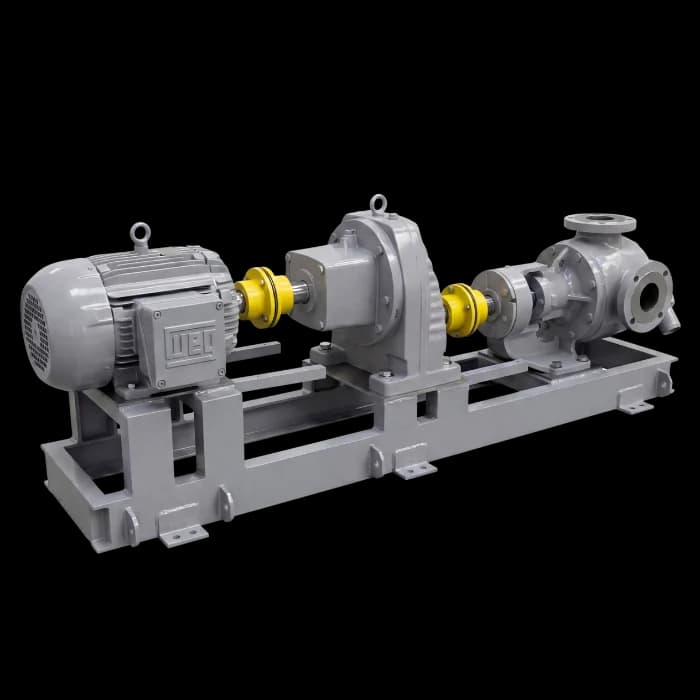
An assembly with a speed reducer is a supply option to discuss with the technical team. Share the fluid, viscosity, temperature, flow and pressure for pump and drive selection.
FBEI-LS identifies the 3″ size in the product catalog, corresponding to LS3 in the dimensional manual. This assembly image does not identify an exact LS3 configuration.
Product catalogues and the MAN001-10 manual are available in Portuguese. Check the configuration before installing or specifying the equipment.
Product catalogues
These catalogues complement the technical manuals. For sizing and operating limits, consult the specific documentation and engineering team.
Installation, operation, maintenance, parts and dimensions for the FBEI series.
The manual lists 40–80 mesh depending on the model. Confirm the filter for the fluid and suction conditions, and check the coupling manufacturer’s requirements. Verify alignment after installing the assembly on its final base.
Check the equipment configuration. Pumps without a relief valve require external protection under the manual. The relief valve must not be used to control pressure or flow.
Configurations, documentation and technical purchasing information.
It is a positive-displacement pump with two internally meshing gears. For FBEI, the manual identifies the rotor with shaft, internal gear and geometry separating suction from discharge. Chambers carry liquid during rotation; selection requires fluid and duty-point data.
The catalog positions FBEI for viscous-liquid transfer. To assess oil, resin, adhesive, paint or another product, provide composition, viscosity at startup and during operation, temperature, solids, and material and sealing requirements. Compatibility depends on the selected configuration, not just the fluid name.
Compare fluid, viscosity, flow, differential pressure, speed, materials and installation space. The FBEI catalog describes internal gears, self-priming and reversibility, but does not provide a comparative pulsation, noise or shear test against FBE. Request selection for your duty rather than assuming universal superiority of either technology.
The catalog describes elevated-temperature duties subject to configuration. This is distinct from the optional jacket: MAN001-10 p.4 specifies steam up to 185 °C and 10 bar or thermal fluid up to 232 °C and 10 bar for its circuit. Confirm pumped-fluid, material, sealing and heating limits for the proposed model.
In the FBEI catalog, LS identifies the 3″ nominal size, corresponding to model LS3 in MAN001-10. The catalog publishes a maximum flow of 45 m³/h for this size; the applicable flow depends on operating conditions. LS does not designate a separate large-capacity family. Supply with motor and speed reducer must be specified with the technical team.
The FBEI catalog lists an assembly with motor and speed reducer among the supply options. The drive type and specification depend on process conditions. Share the fluid, viscosity, temperature, flow, pressure and operating regime for assessment by the technical team.
FBEI is the FB Bombas internal gear pump series for transferring viscous liquids. MAN001-10 documents ten models from 1″ to 4″; the current catalog presents six sizes from 1½″ to 6″. These documents have different coverage. Materials, sealing, drive and accessories are specified for the fluid and operating conditions.
Compare the duty point and drawings of the installed pump and proposed configuration: connections, flanges, shaft height, mounting and drive. Size or series name does not establish interchangeability. MAN001-10 provides ten dimensional models; the current catalog presents six sizes, including N 6″. Request installation data for N from the technical team.
Model pages use three MAN001-10 drawings: Fig.8 for HL12, KK2, LQ21, LS3 and M4; Fig.11 for GG1 and HJ12; Fig.12 for AS3, AK3 and AL3. The manual also shows HL12 in Fig.11 with different dimensions; this site’s HL12 page uses Fig.8. These dimensional groups alone do not establish materials, reinforced construction or accessories for every supplied pump.
To assess asphalt, bitumen or heavy oil, provide composition, solids content, viscosity at startup and operating temperatures, flow and pressures. The catalog positions FBEI for viscous-liquid transfer; suitability for a specific product depends on materials, sealing, heating and drive selection. A fluid name does not automatically approve every model.
The catalog lists body and support options in cast iron, ductile iron, carbon steel and stainless steel. Bronze is among the bushing options. The manual shows mechanical seal and packing; the catalog also lists single, double and cartridge seals. Confirm alloy, sealing and availability for the specified configuration and fluid.
MAN001-10 covers identification, parts, dimensions, transport, storage, installation, operation and alignment. The available edition is revision 00, dated 27 September 2010, in Portuguese. It contains conflicting startup instructions on pages 5 and 13; confirm the applicable procedure with technical support rather than following an isolated PDF sequence. The current catalog supplements series options and does not replace the supplied equipment data sheet.
The MAN001-10 p.7 exploded view identifies the rotor with shaft and the internal gear. The crescent geometry separates suction and discharge paths, transferring liquid by positive displacement. For a sensitive fluid, state temperature and product-change limits; the construction principle alone does not establish low shear, noise or pulsation for every duty.
Check protection in the supplied configuration. The catalog lists a relief valve among series items; MAN001-10 p.4 requires external protection when the pump has no relief valve. Relief must not regulate pressure or flow or remain open for prolonged periods. Confirm the setting, orientation and startup procedure for the installation.
For technical procurement, request the current supplier registration and check its validity, product families and covered requirements. Petrobras uses the Certificado de Registro Cadastral (CRC), which replaced CRCC. Registration qualifies the supplier against the stated criteria; it does not automatically certify an FBEI pump or the whole series. Check the documents applicable to the quoted supply.
Lead time is stated in the quotation based on model, materials, sealing, drive, accessories and documentation scope. Compare equivalent quotations, including freight and delivery terms. Factory location alone does not establish stock availability or a shorter lead time than another option.
The FBEI technical quotation is requested directly from the application engineering team. Provide the fluid (with viscosity and temperature), required flow, discharge pressure, available NPSH and desired materials. The official technical manual MAN001-10 — with dimensions of all 10 catalogued models, operating principle, sealing options, installation requirements and recommended spare parts — is available free at /en/technical-manuals/fbei. The PDF is in Portuguese; the website reference pages are trilingual.
Share your fluid and operating conditions. Our team uses these details to assess the model, sealing and drive for your application.
Size and weight do not determine flow, pressure, speed or power. These values depend on application sizing.
The series presents the equipment; technical resources explain selection and operation in more detail.