

FB Bombas Engineering Team10 min read
Identify the series, full model and installed shaft seal. FBE shafts run in bushings; a rolling bearing is only fitted in the optional external bracket. FBEI has a rotor, bearing and its own packing, monitoring and storage requirements. Use the configuration-specific parts list.
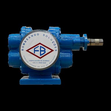
FB Bombas pump for this application
Need parts for your gear pump?
FBE parts lists differ by size, shaft seal and accessories. The full model and installed shaft seal identify which list to use for a spare parts enquiry.
Source: Manual FBE MTEC-01/01, pp.8–15, listas de peças
What changes between FBE and FBEI maintenance
Plan gear pump maintenance around the installed series. Photograph the nameplate and retain the full model designation. On the FBE, CA identifies a heating chamber, D a longer gear, and DA a gear with greater length and module. The FBEI nameplate is on top of the casing.
| Item | FBE | FBEI |
|---|---|---|
| Construction | External helical gears mounted one above the other. | Internal gear construction; rotor and shaft assembly. |
| Shaft support | Bushings; rolling bearing only in the optional external bracket. | Bearing and bushings identified in the parts list. |
| Shaft seal parts lists | Packing, mechanical seal and lip seal lists, according to configuration. | Separate packing and mechanical seal lists with different item numbers. |
FBE: bushings and parts by shaft seal
The FBE shaft has no sleeve at the sealing area. On packed pumps, a hexagonal nut adjusts the packing gland. The parts lists distinguish sizes and variants; retain the model suffixes when looking up components.
The packed FBE 1/8″–1/4″, 1″D–1″DA and 1.1/2″–3″ lists specify four bushings, reference 540. Packing quantities vary between the groups below. The standard materials list specifies graphited packing for cast iron, ductile iron and carbon steel, and PTFE-treated packing for stainless steel and bronze.
- Gears in Table 10: each reference has one part on the FBE 1.1/2″ and two on the FBE 2″ and 3″.
- Standard mechanical seal: type 21, ceramic × graphite × Viton, with an AISI 304 spring. Table 12 places the seal in the casing on 1/2″–1″ pumps and the rear cover on 1″D–4″ pumps.
- Lip seal: requires a cover or casing with a dedicated seal housing. Table 13 lists two units, reference 421.
| Packed model | Packing quantity |
|---|---|
| 1/8″–1/4″ | 4 |
| 3/8″–1″ | 4 |
| 1″D–1″DA | 5 |
| 1.1/2″–3″ | 5 |
FBE: identify accessories and connections
The FBE rolling bearing belongs to the optional external bearing bracket. The heating chamber and relief valve also have their own parts lists. Record which accessories are fitted to select the corresponding lists.
FBE rotation is clockwise, with a counterclockwise option, viewed from the drive end. Keep the installed configuration identified when planning the return to service.
| Assembly or connection | Identification reference |
|---|---|
| Optional external bearing bracket | 321 — rolling bearing; 330 — bearing bracket. |
| Relief valve | 756 — spring; 757 — adjusting screw; 924 — adjusting nut. |
| F1 / Q1 | Seal flush / quench, only as required by the application and request. |
| C1 / C2 | Heating chamber inlet / outlet. |
FBEI: rotor, bearing and shaft seal parts lists
FBEI item numbers differ between the mechanical seal and packing lists. The rotor and shaft are item 18 on the mechanical seal version and item 22 on the packed version. Packing is item 13 in its list. Always give the shaft seal type with the part number.
Keep drive lubrication separate from pump component identification. Before starting the FBEI, check the gearbox oil level and top it up if needed, following the gearbox manufacturer’s instructions. The pump parts list separately identifies the bearing, grease fitting and bushings.
| Mechanical seal version component | Item |
|---|---|
| Bearing | 6 |
| Mechanical seal with gland plate | 10 |
| Grease fitting | 12 |
| Support bushing | 14 |
| Rotor and shaft | 18 |
| Internal gear | 19 |
| Internal gear bushing | 20 |
FBEI: packing adjustment and monitoring
On the packed FBEI, leave the gland nuts just in contact before operation. The packing must drip while the pump runs. This requirement continues after the initial bedding-in period.
| Stage | Action |
|---|---|
| Packing adjustment | Tighten the gland nuts by about 1/6 of a turn. |
| First 5 to 8 hours | Observe the packing. If leakage is excessive, tighten by about a further 1/6 of a turn. |
| After bedding-in | Check the packing weekly. |
Engineering note
The weekly check in this section applies to FBEI packing. Dripping is part of its operation; the end of bedding-in is not an instruction to eliminate it.
FBEI: record conditions during the first hours
Monitor motor current, supply voltage, suction pressure, bearing temperature and any abnormal noise or vibration. Suction pressure must match the design value. Include packing observations where this shaft seal is fitted.
| Check | Reference |
|---|---|
| First 2 hours | Check the listed items every 15 minutes. |
| If readings remain normal | Continue with hourly checks through the first 5 to 8 hours. |
| Bearing temperature | Up to 50 °C above ambient, without the resulting temperature exceeding 90 °C. |
Warning
The FBEI relief valve must not control pressure or flow. Prolonged operation with it open can overheat and damage the pump.
FBEI: prepare the return-to-service records
The FBEI must operate under the conditions for which it was sized. Use those conditions when organising checks of the shaft seal, drive and auxiliaries. Keep a copy of the manual accessible to the person responsible for maintenance.
- Mechanical seal: check adjustment, removal of air from the seal area, and connection of accessories and auxiliary fluids.
- Drive: check rotation direction with the pump uncoupled. Check that the shaft turns easily through at least one full manual revolution and fit the coupling guard.
- Heating: supply the jackets gradually to avoid thermal shock. The fluid inside must be at the appropriate temperature and viscosity before startup.
- Suction: check that piping is clean and free of unwanted particles. If a permanent strainer cannot be installed, fit a temporary conical strainer before testing or startup.
- Protection: an FBEI without a relief valve requires a protective system, such as a line valve, pressure switch or torque limiter.
Warning
Never operate the FBEI without liquid inside. These checks record preparation conditions; use the startup sequence confirmed for the equipment.
FBEI: storage and renewed preservation
During storage, keep the FBEI free from moisture, dust, vapours and high salinity, under a waterproof protective covering. Plan how the shaft seal and openings will be protected before packing the equipment.
- Remove the packing before storing the pump.
- Clean mechanical seals with dry air. Do not apply liquid during cleaning for storage, to avoid damaging seals and gaskets.
- Close the suction and discharge flanges and cap auxiliary connections to prevent foreign material entering.
| Condition | Preservation action |
|---|---|
| Awaiting operation | Turn the rotating assembly every 15 days. |
| Stored for more than one year | Schedule renewed preservation every 12 months, including disassembly and cleaning, using the procedure for the configuration. |
Warning
Do not use steam or water to clean the FBEI or the system. When transporting the complete assembly, do not lift it using only a pump or motor lifting eye.
FBEI: spares for two years of operation
For FBEI inventory planning, the spare parts reference for two years of operation includes the components below. This period guides the stocking list; it does not define component service life or require all parts to be replaced at its end.
- Internal gear.
- Pin.
- Support bushing and internal gear bushing.
- Sealing set: packing or mechanical seal, and bearing.
Send equipment identification and maintenance scope
Prepare the enquiry:
- send the series, full model, serial number and nameplate photo;
- identify the installed shaft seal and accessories;
- give the part name, number and parts list used;
- describe the fluid, operating conditions and symptom, with available readings.
Ask FB Bombas Engineering for the configuration-specific information still needed to complete the plan:
- Lubricant, quantity and interval for the fitted components; clearances, wear limits, tightening torques and disassembly and assembly procedures.
- Shaft seal material and adjustment, acceptable leakage criterion, temperature conditions and protection settings; inspection schedule for other components.
- Isolation, decontamination, post-repair startup and acceptance procedures; preservation product and full preservation or renewed preservation process, including return from storage.