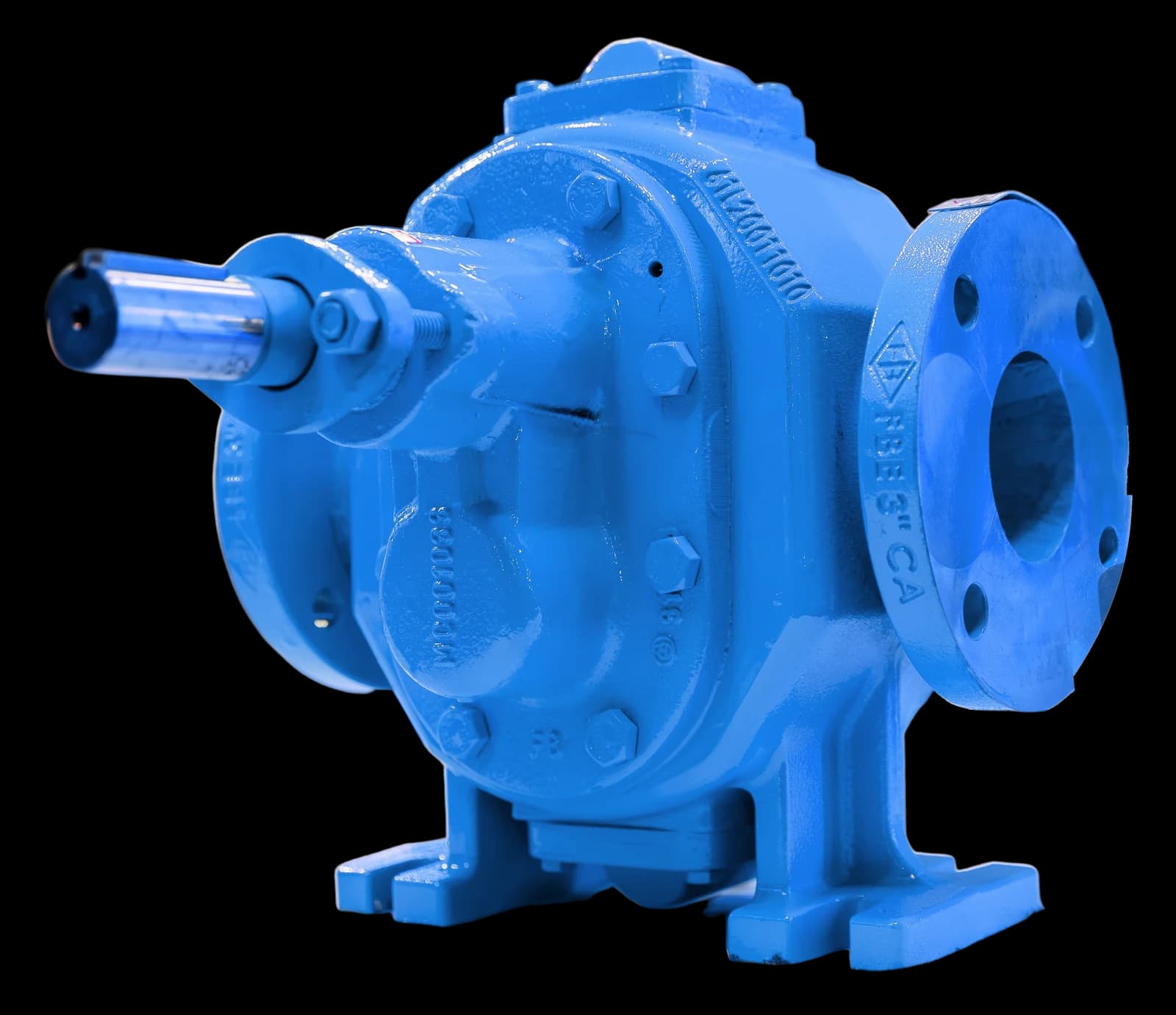
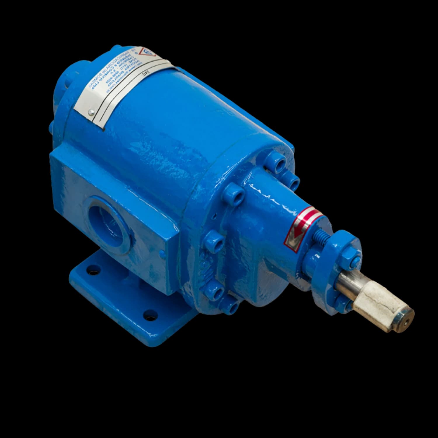
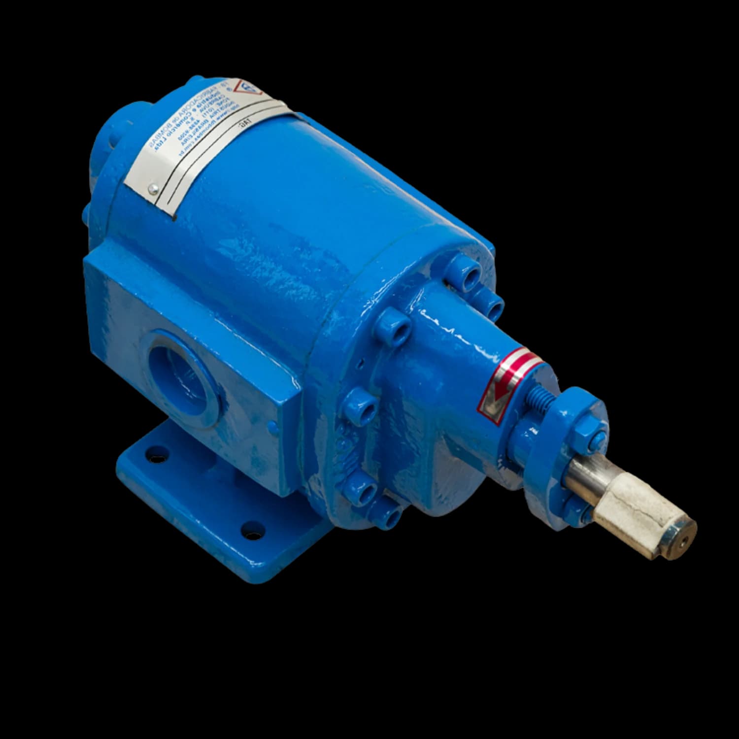
FBE 1/8″
View datasheet and curve for FBE 1/8″- Max. flow
- 5.15 L/min
- Max. pressure
- 22 kgf/cm²
- Max. speed
- 1,750 rpm

The FBE external gear pump transfers viscous fluids by positive displacement. Compare models and consult the curves, materials and sealing options.
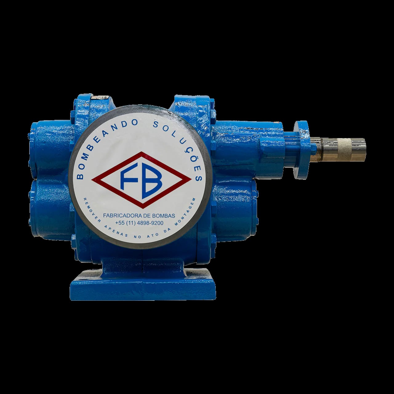
FBE in stock at the factory
FBE 1/8″–4″ · In every configuration and option.
Availability and pricing are confirmed by our team.
The FBE is the external gear pump from FB Bombas, a Brazilian manufacturer since 1944, in Cabreúva, SP. Choose the connection size and open the model datasheet to check dimensions and curves.
20 catalog models · 12 sizes
Each card shows the model’s maximum flow, pressure and speed. These maxima do not apply simultaneously: the conditions are on the model’s datasheet. For the operating principle, see the guide external gear pump.
Each band links the fluid viscosity to the working speed and to the sizes in the series.
Viscosity30 to 250 SSU
Speed1,750 rpm
SizesFBE 1/8″, 1/4″, 3/8″, 1/2″, 3/4″ and 1″
Viscosity250 to 2,500 SSU
Speed1,150 rpm
SizesFBE 1/8″, 1/4″, 3/8″, 1/2″, 3/4″, 1″, 1.1/2″, 2″, 3″, 4″ and 5″
Viscosity2,500 to 7,500 SSU
Speed850 rpm
SizesFBE 3/8″, 1/2″, 3/4″, 1″, 1.1/2″, 2″, 3″, 4″ and 5″
Viscosity7,500 to 10,000 SSU
Speed700 to 500 rpm with a pulley or gear reducer
SizesFBE 1.1/2″, 2″, 3″, 4″ and 5″
Viscosity10,000 to 50,000 SSU
Speed500 to 300 rpm with a pulley or gear reducer
SizesFBE 1.1/2″, 2″, 3″, 4″, 5″ and 6″
Viscosity50,000 to 100,000 SSU
Speed300 to 150 rpm with a pulley or gear reducer
SizesFBE 3″, 4″, 5″ and 6″
Logarithmic scale, from 30 to 100,000 SSU.
The bars compare each size with the series maximum: 100,000 SSU viscosity and 1,750 rpm speed.


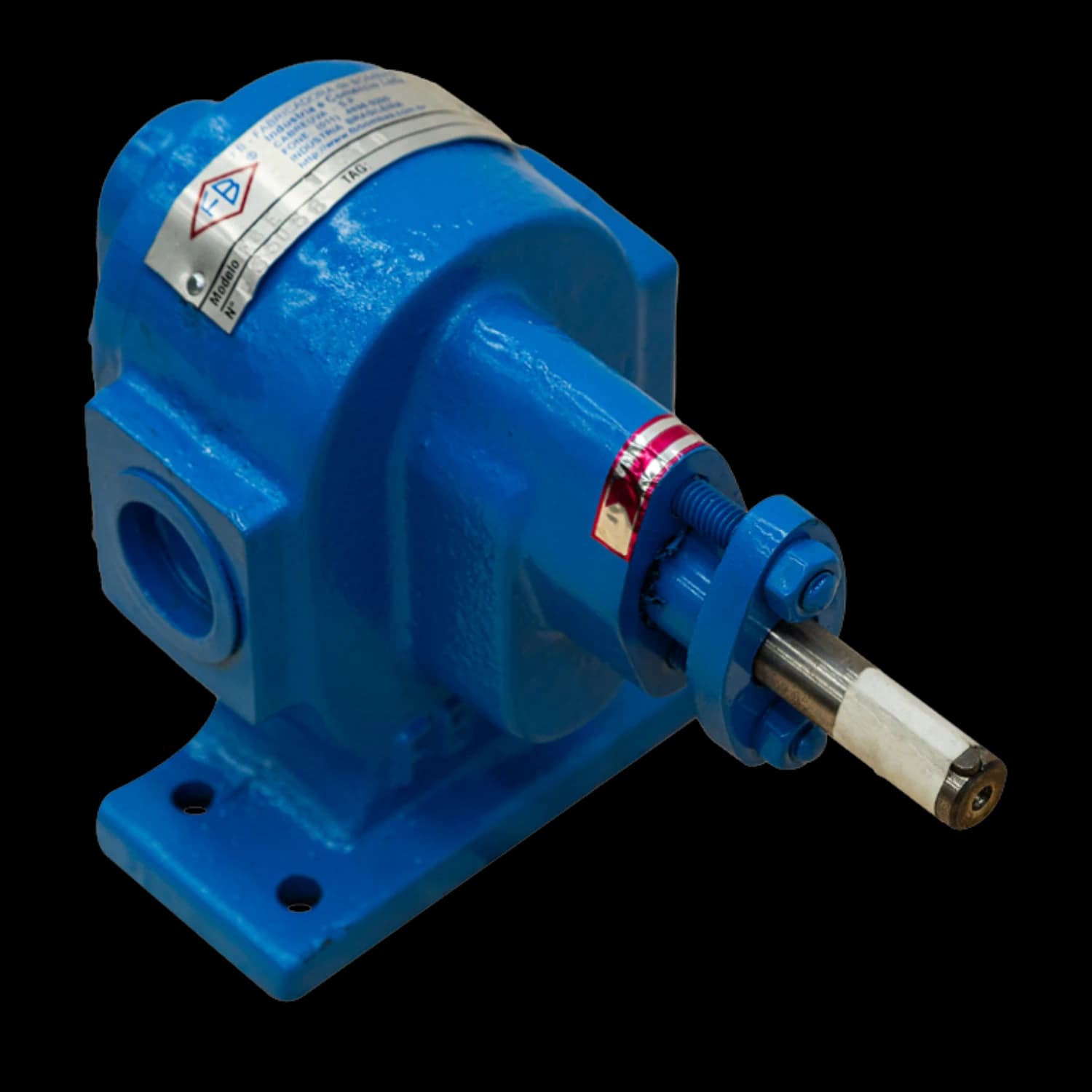
Optional heating chamber
Optional heating chamber
Optional heating chamber
Optional heating chamber
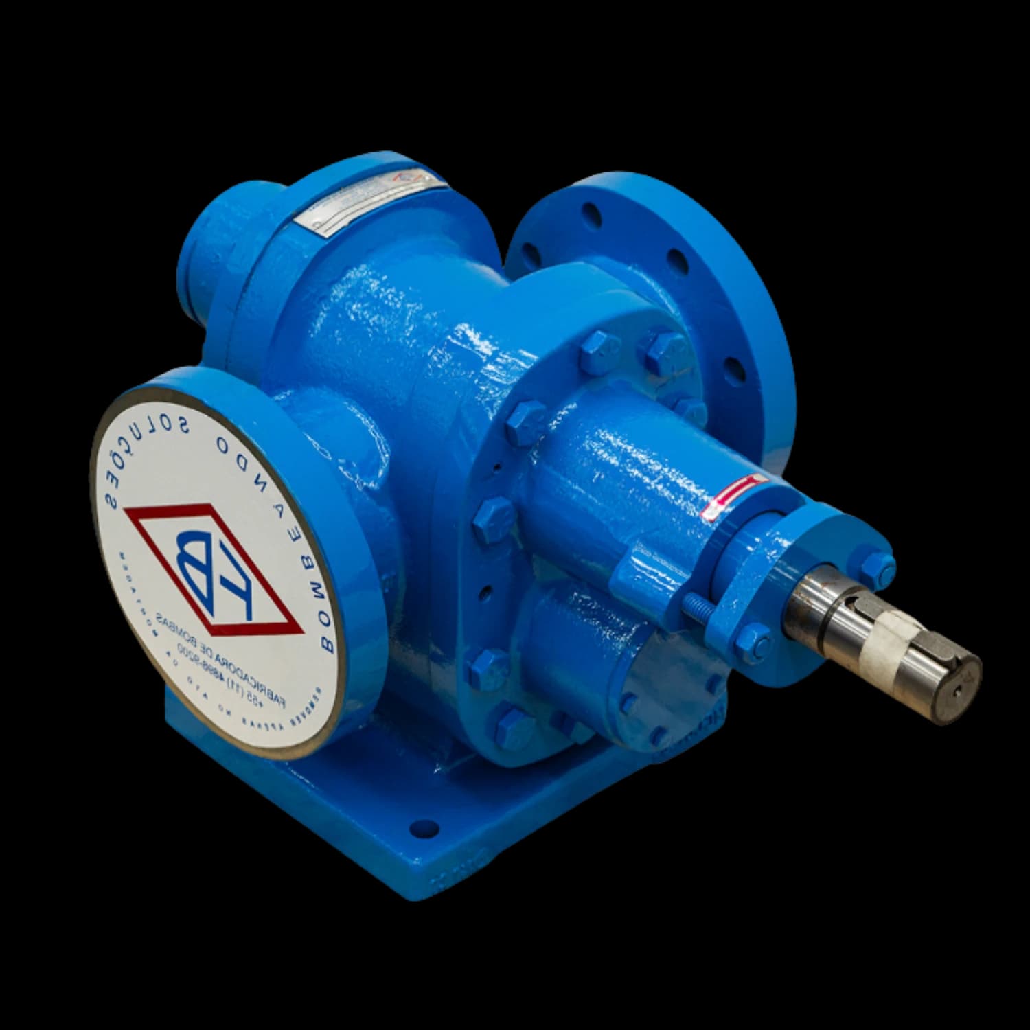
For the FBE 5″ and FBE 6″, check availability with our team.
Optional heating chamber
The 2026 FBE catalogue lists the 10″ model on p.6. Larger models are made to order. Contact our technical team to confirm the configuration, dimensions and operating conditions for your application.
Selection depends on the fluid, speed, duty point and configuration.
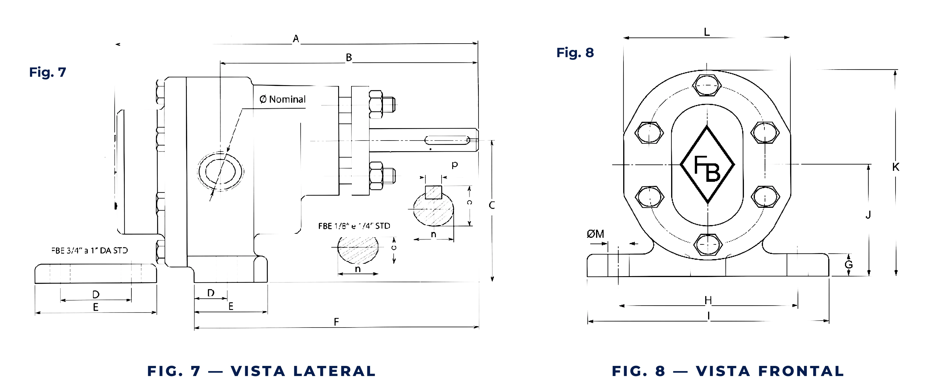
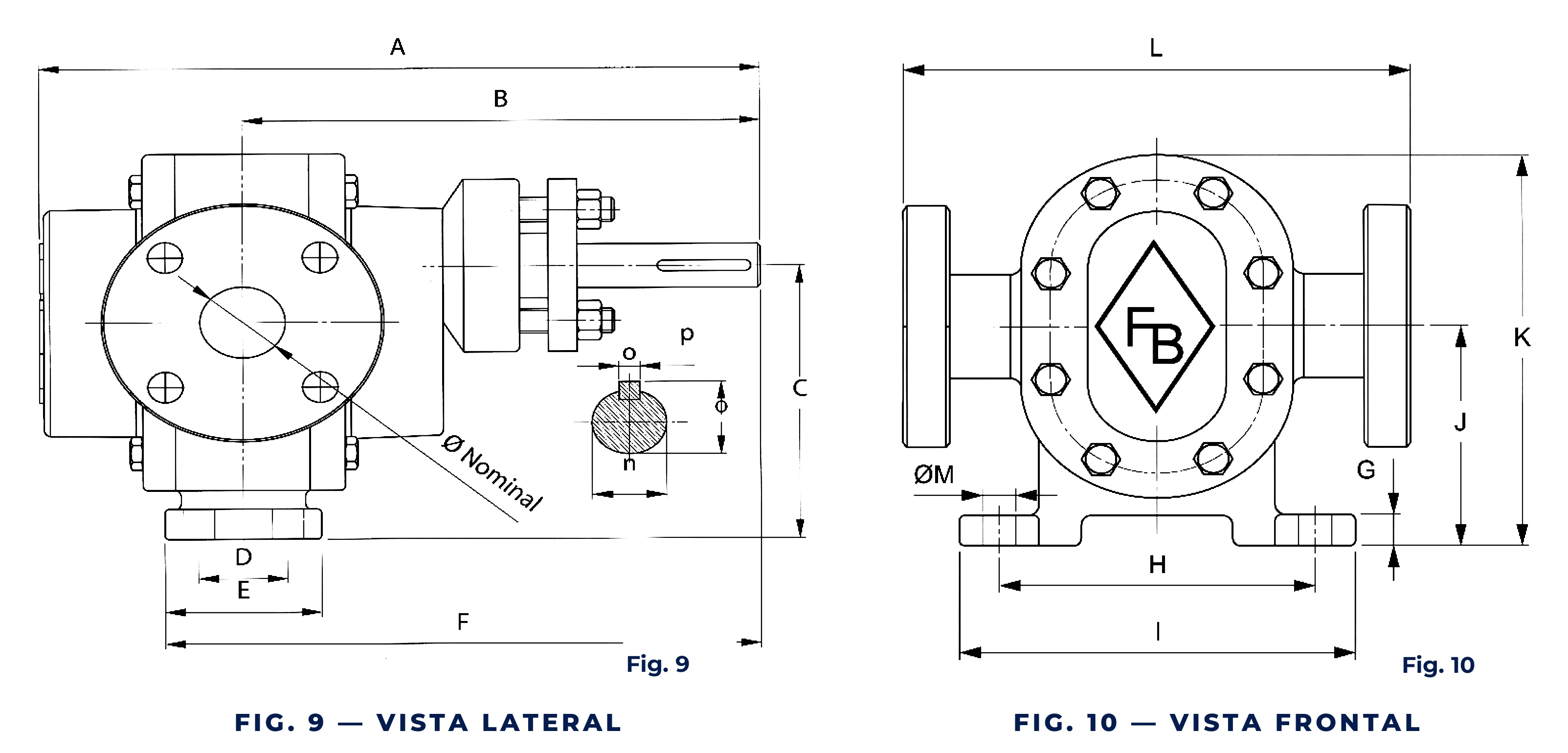
Compare installation dimensions by model and use the figure to identify each letter. Each model link opens its dimensional section.
 Enlarge figure
| Model | Nominal Ø | Dimensions A–F | Shaft end | Dimensions G–M | Weight (kg) | |||||||||||||
|---|---|---|---|---|---|---|---|---|---|---|---|---|---|---|---|---|---|---|
| A | B | C | D | E | F | n | o | p | G | H | I | J | K | L | M | |||
| FBE 1/8″ STD | 1/8″ | 148,5 | 102 | 49 | 13 | 26 | 111,5 | 12 | 11 | Not applicable | 7 | 45 | 65 | 37 | 74 | 50 | 8 | 1,9 |
| FBE 1/4″ STD | 1/4″ | 148,5 | 102 | 49 | 13 | 26 | 111,5 | 12 | 11 | Not applicable | 7 | 45 | 65 | 37 | 74 | 50 | 8 | 1,9 |
| FBE 3/8″ STD | 3/8″ | 163 | 115,5 | 75 | 15 | 33 | 127,5 | 12 | 14,3 | 3/16″ | 12 | 80 | 108 | 59 | 109 | 75 | 9,5 | 2,7 |
| FBE 1/2″ STD | 1/2″ | 163 | 115,5 | 75 | 15 | 33 | 127,5 | 12 | 14,3 | 3/16″ | 12 | 80 | 108 | 59 | 109 | 75 | 9,5 | 2,7 |
| FBE 3/4″ STD | 3/4″ | 205 | 144 | 104 | 32 | 55 | 164 | 9/16″ | 16,6 | 3/16″ | 10 | 102 | 130 | 83 | 147 | 110 | 9 | 6,5 |
| FBE 1″ e 1″ A STD | 1″ | 219 | 154 | 104 | 32 | 55 | 170 | 9/16″ | 16,6 | 3/16″ | 10 | 102 | 130 | 83 | 147 | 110 | 9 | 6,7 |
| FBE 1″ D e 1″ DA STD | 1″ | 273 | 184 | 103,15 | 52 | 80 | 224 | 5/8″ | 17,6 | 3/16″ | 11 | 90 | 115 | 83 | 146 | 110 | 9 | 11,5 |
D: from 1/8″ to 1/2″, base edge to hole centre; from 3/4″ to 4″, between hole centres (Fig. 7 and 9).
No key (p = –): in Fig. 7, "o" is the shaft end measured over its flat.
 Enlarge figure
| Model | Nominal Ø | Dimensions A–F | Shaft end | Dimensions G–M | Weight (kg) | |||||||||||||
|---|---|---|---|---|---|---|---|---|---|---|---|---|---|---|---|---|---|---|
| A | B | C | D | E | F | n | o | p | G | H | I | J | K | L | M | |||
| FBE 1.1/2″ e 1.1/2″ A STD | 1.1/2″ | 324 | 232 | 145 | 40 | 70 | 267 | 23 | 26,15 | 1/4″ | 16 | 140 | 175 | 115 | 205 | 222 | 14 | 26 |
| FBE 1.1/2″ CA e CA-A STD | 1.1/2″ | 374,9 | 252,9 | 177 | 80 | 114 | 309,9 | 23 | 26,15 | 1/4″ | 15 | 164 | 199 | 147 | 290 | 255 | 14 | 40 |
| FBE 2″ e 2″ A STD | 2″ | 382 | 260 | 145 | 70 | 110 | 315 | 23 | 26,15 | 1/4″ | 20 | 150 | 190 | 115 | 205 | 228 | 14 | 39 |
| FBE 2″ CA e CA-A STD | 2″ | 382 | 260 | 165 | 80 | 115 | 317,5 | 23 | 26,15 | 1/4″ | 15 | 164 | 200 | 135 | 267 | 263 | 14 | 43 |
| FBE 3″ e 3″ M9 STD | 3″ | 429 | 290 | 170 | 80 | 120 | 350 | 32 | 34,97 | 5/16″ | 18 | 180 | 220 | 125,2 | 248 | 324 | 18 | 70 |
| FBE 3″ CA e 3″ M9 CA STD | 3″ | 449 | 300 | 226,8 | 86 | 140 | 370 | 32 | 34,94 | 5/16″ | 18 | 210 | 260 | 182 | 360 | 330 | 18 | 83 |
| FBE 4″ M6, M8 e M12 STD | 4″ | 583 | 390 | 251 | 194 | 240 | 509 | 42 | 46 | 3/8″ | 35 | 214 | 270 | 200 | 347 | 361 | 18 | 130 |
| FBE 4″ M6, M8 e M12 CA STD | 4″ | 583 | 390 | 260,7 | 110 | 170 | 474 | 42 | 46 | 3/8″ | 20 | 260 | 310 | 210 | 418,7 | 360 | 19,05 | 148 |
D: from 1/8″ to 1/2″, base edge to hole centre; from 3/4″ to 4″, between hole centres (Fig. 7 and 9).
The FBE is the FB Bombas external gear positive displacement pump, selected by size, gear set, viscosity and speed. Casing and covers: cast iron, ductile iron, carbon steel, stainless steel or bronze; shafts and gears: SAE 1045 steel or AISI 316L stainless. Sealing is packing, mechanical seal or lip seal; heating chamber, relief valve and external bearing support are accessories.
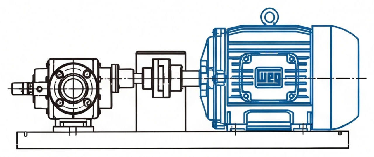
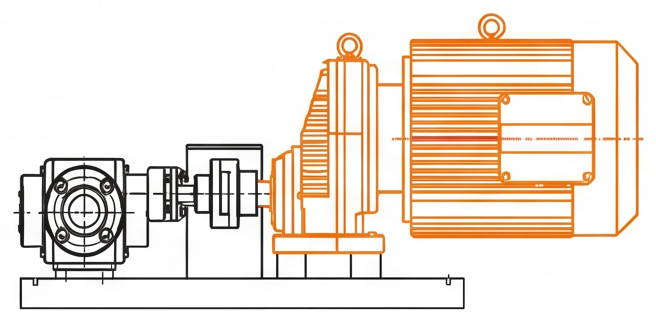
FBE can be supplied with an electric motor or geared motor, on a metal base with a flexible coupling. The arrangement is specified for speed, fluid and installation conditions.
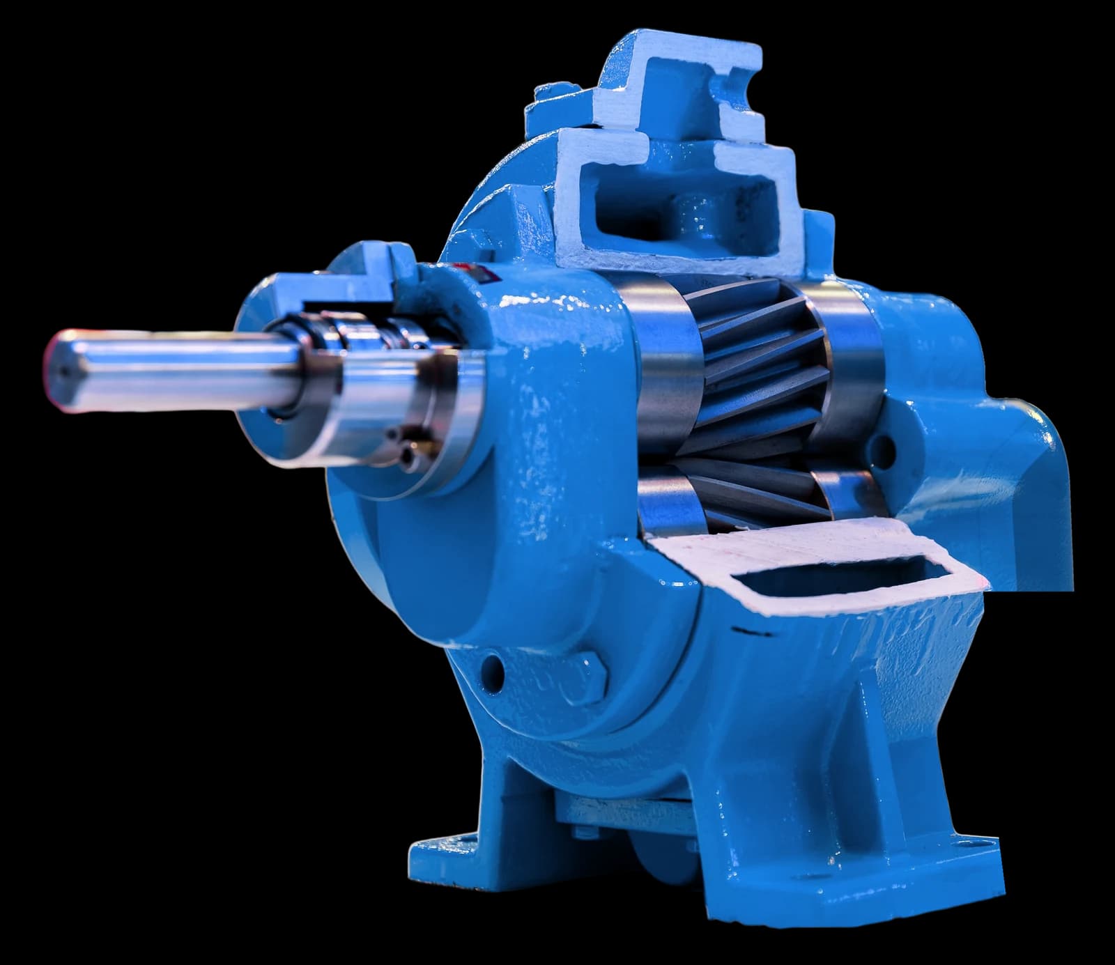
Two external gears carry the fluid in the cavities between the teeth and casing, from suction to discharge. Selection considers the fluid, speed and gear set.
Oils, greases, asphalt and derivatives, according to process conditions.
Paints, varnishes, resins, cosmetics and detergents, with materials and sealing selected for the fluid.
Milk, syrups, molasses, butters, jams, gelatin, glucose, BPF oil, vegetable oil, citrus, soft drinks, aromatic essential oils, ferments and yeast.
Hydraulic systems, filter presses and lubrication.
Assembly selection based on the fluid and process conditions.
Configuration specified for the pumped product and operating conditions.
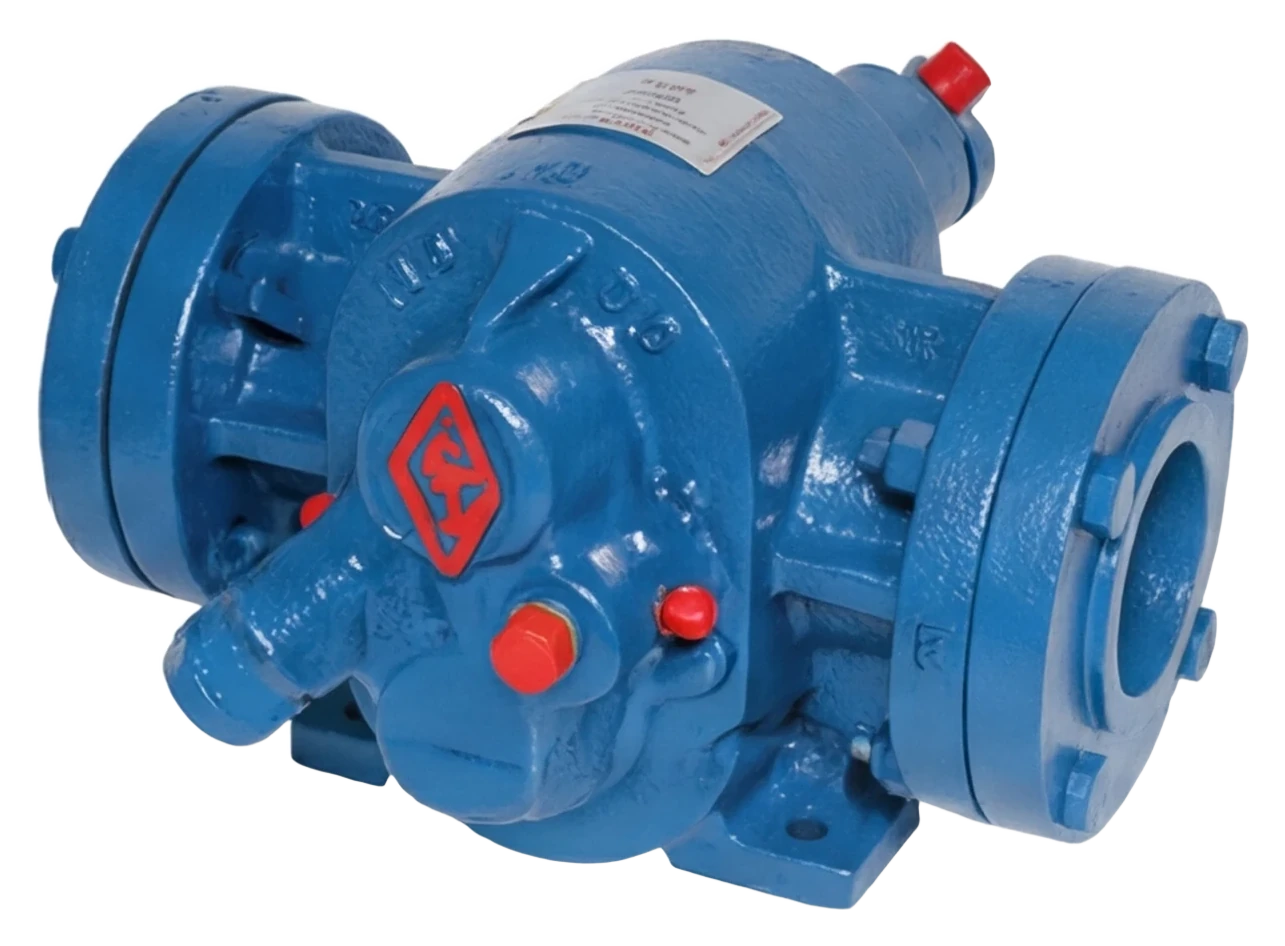
The FBE series is built in cast iron with a relief valve, in bronze and in stainless steel. The captions give the size and the type of configuration; the material of each component is in the table that follows.
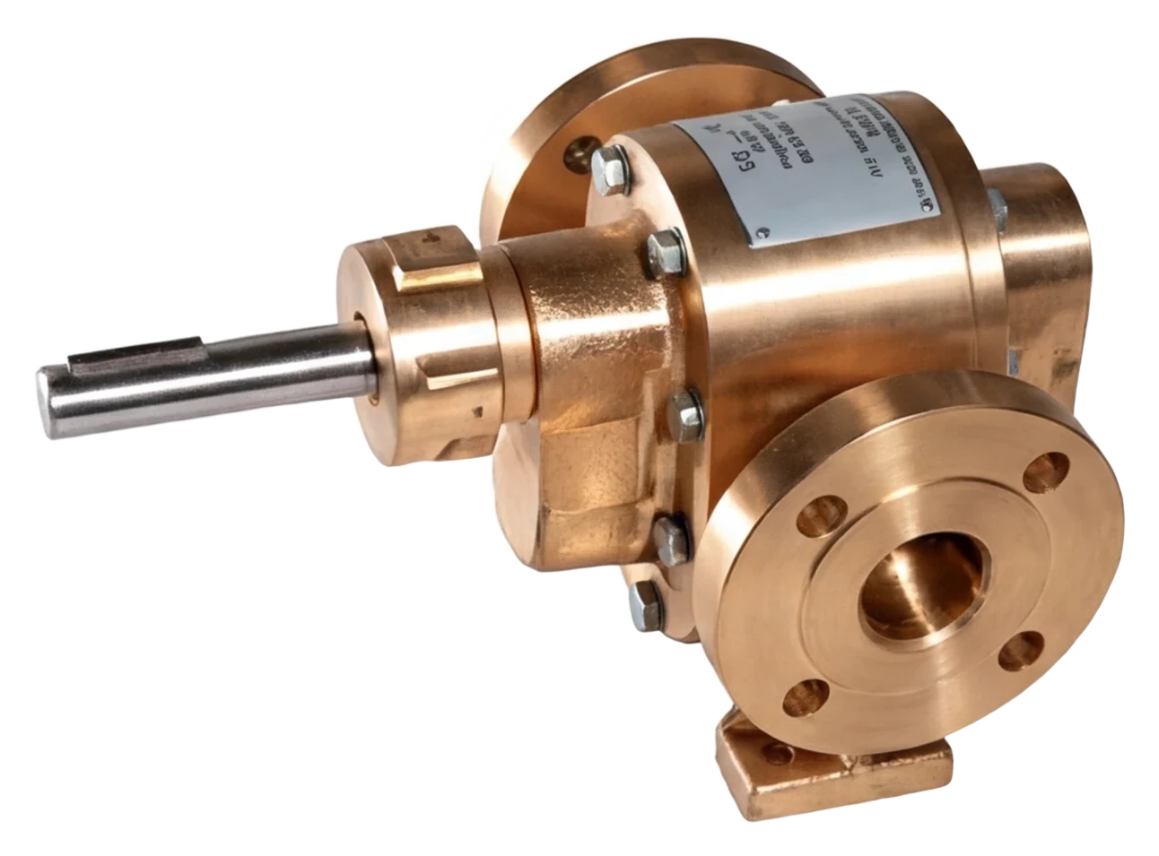
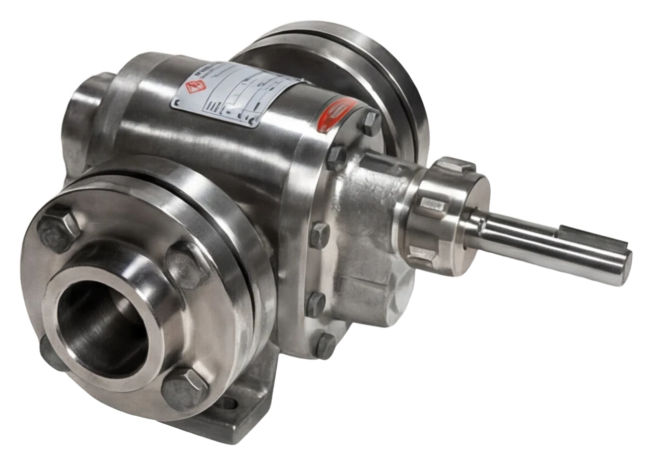
The FBE casing and covers are ASTM A48 CL30 cast iron, ASTM A536 60-40-18 ductile iron, ASTM A216 WCB carbon steel or ASTM A743 CF8M stainless steel, and the shafts and gears are SAE 1045 steel or AISI 316L stainless steel. The bronze configuration uses ASTM B584 C93700, and the table by configuration follows.
| Component | Material options | Designation |
|---|---|---|
| Casing and covers Bronze is a configuration of its own in the series; its composition is in the table by configuration below. | Cast iron | ASTM A48 CL30 |
| Ductile iron | ASTM A536 60-40-18 | |
| Carbon steel | ASTM A216 WCB | |
| Stainless steel | ASTM A743 CF8M | |
| Bronze | ASTM B584 C93700 (SAE J462 64) | |
| Shafts and gears Special treatments on request. In the bronze configuration the shafts are AISI 316 and the gears SAE J462 63. | Steel | SAE 1045 |
| Stainless steel | AISI 316L | |
| Bronze, gears | SAE J462 63 | |
| Bronze, shafts | AISI 316 | |
| Bushings | Self-lubricating bronze | — |
| Cast iron | — | |
| PTFE (Teflon) | — | |
| Graphite | — | |
| White metal (metal patente) | — | |
| Relief valve | Brass | — |
| Stainless steel | AISI 304 |
Each column is a pump configuration (cast iron, ductile iron, carbon steel, stainless steel, bronze). The ASTM, SAE and AISI designations identify each material. FB Bombas confirms the composition of each supply in the quotation.
| Component | Cast iron | Ductile iron | Carbon steel | Stainless steel | Bronze |
|---|---|---|---|---|---|
| Casing | ASTM A48 CL30 | ASTM A536 60-40-18 | ASTM A216 WCB | ASTM A743 CF8M | ASTM B584 C93700 (SAE J462 64) |
| Front and rear cover | ASTM A48 CL30 | ASTM A536 60-40-18 | ASTM A216 WCB | ASTM A743 CF8M | ASTM B584 C93700 (SAE J462 64) |
| Plug (for chamber) | ASTM A48 CL30 | ASTM A536 60-40-18 | ASTM A216 WCB | ASTM A743 CF8M | ASTM B584 C93700 (SAE J462 64) |
| Bushing | Bronze TM 23 | Graphite | Bronze TM 23 | Teflon | Teflon |
| Drive shaft | SAE 1045 | SAE 8620 | SAE 1045 | AISI 316La | AISI 316 |
| Driven shaft | SAE 1045 | SAE 8620 | SAE 1045 | AISI 316La | AISI 316 |
| Drive gear | SAE 1045 | SAE 8640 | SAE 1045 | AISI 316La | SAE J462 63 |
| Driven gear | SAE 1045 | SAE 8640 | SAE 1045 | AISI 316La | SAE J462 63 |
| Bolts | Steel 5.8 | Steel 5.8 | Steel 5.8 | AISI 304 | AISI 304 |
| Nuts | Steel 5.8 | Steel 5.8 | Steel 5.8 | AISI 304 | AISI 304 |
| Gland follower | ASTM A48 CL30 | ASTM A536 60-40-18 | ASTM A216 WCB | ASTM A743 CF8M | ASTM B584 C93700 (SAE 64) |
| Packing ring | Graphite-impregnated | Graphite-impregnated | Graphite-impregnated | PTFE-impregnated | PTFE-impregnated |
| Relief valve | Brass | AISI 304 | Brass | AISI 304 | AISI 304 |
| Mechanical seal | As required by the application | As required by the application | As required by the application | As required by the application | As required by the application |
| Gland plate | SAE 1020 | AISI 304 | SAE 1020 | AISI 304 | AISI 304 |
| Spring retainer | SAE 1020 | AISI 304 | SAE 1020 | AISI 304 | AISI 304 |
| Dowel pin | Steel | Steel | Steel | AISI 304 | AISI 304 |
| Plug | SAE 1045 | SAE 1045 | SAE 1045 | AISI 304 | AISI 304 |
| Keys | SAE 1045 | SAE 1045 | SAE 1045 | AISI 304 | AISI 304 |
| Outer cover | ASTM A48 CL30 | ASTM A536 60-40-18 | ASTM A216 WCB | AISI 304 | AISI 304 |
| Flow reducer | ASTM A48 CL30 | ASTM A536 60-40-18 | ASTM A216 WCB | AISI 304 | AISI 304 |
| Flange | SAE 1020 | AISI 304 | SAE 1020 | AISI 304 | AISI 304 |
| Counter flange | ASTM A48 CL30 | ASTM A536 60-40-18 | ASTM A216 WCB | ASTM A743 CF8M | ASTM B584 C93700 (SAE J462 64) |
This is the standard composition of each configuration. The quotation confirms the composition of each supply.
Note a: for stainless steel shafts and gears the current offer is AISI 316L. In the Bronze column the shafts are AISI 316.
As an option, shafts can be SAE 8620 and gears SAE 8640, or another material, depending on the application.
FB Bombas also supplies cast iron and white metal (metal patente) bushings.
The FBE shaft is sealed with packing, a mechanical seal or a lip seal, selected for the application of the pumped fluid, and sits at the front of the pump.
| Feature | Packing | Mechanical seal | Lip seal |
|---|---|---|---|
| How it is fitted | PackingInstalled in the stuffing box, pressed by a gland follower and adjusted by a hexagon nut. | Mechanical sealMounted and pressed by the gland plate, which is the housing or seal chamber. | Lip sealInstalled in the cover or casing, specially machined for the housing. |
| Material | Graphite-impregnated on the cast iron, ductile iron and carbon steel configurations; PTFE-impregnated on stainless steel and bronze. | As required by the application. Type 21 is one of the seal options: ceramic x graphite x Viton, AISI 304 stainless steel spring. | Defined on consultation with FB Bombas. |
| Size | Section of 1/8″, 1/4″ or 3/8″, depending on pump size. | Diameter of 5/8″, 7/8″, 1.3/8″ or 1.3/4″, depending on pump size. | Given on request. |
| Parts list coverage | FBE 1/8″ to 4″, with 4 packing rings up to the 1″ and 5 from the 1″ D to the 4″. | FBE 1/2″ to 4″: casing for seal on the 1/2″ to 1″, rear cover for seal on the 1″ D to 4″. | FBE 1/2″ to 4″: casing for lip seal on the 1/2″ to 1″, rear cover on the 1″ D to 4″, with 2 lip seals. |
| Spare part | Gland follower and gland follower nut. | Mechanical seal. | Lip seal. |
Fluid with suspended solids: consult FB Bombas. The shaft has no sleeve in the sealing area.
The gland plate drain and the seal flush and quench connections are made only according to the application and the customer's request.
The FBE offers an internal relief valve, a CA heating chamber and an external bearing support as accessories. Each has its own datasheet below.
Shown here: the 3″ FBE in cast iron with a relief valve.
The CA version has a casing with a chamber, with an inlet (C1) and an outlet (C2).
FBE shafts run in bushing bearings. A rolling bearing exists only in the optional external bearing support.
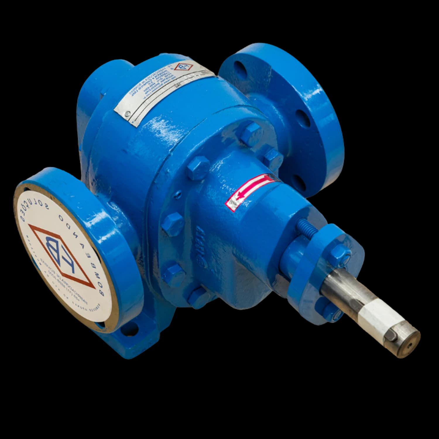
FBE models from 1/8″ to 1″ have a BSP-threaded body, and models from 1.1/2″ to 10″ have a body with ANSI B16.5 150 lb flanges.
| Connection | Models |
|---|---|
| BSP thread | FBE 1/8″ to 1″ |
| ANSI B16.5 150 lb flanges | FBE 1.1/2″ to 10″ |
Confirm the dimensional drawing of the supplied arrangement before specifying piping.
The auxiliary threads (drain, instrument, chamber inlet and outlet, flush and quench) are on the datasheet of each size.FB Bombas supplies the FBE in two drive configurations, direct on an electric motor or direct on a geared motor, both on a metal base with a flexible coupling.
| Power | up to 2 cv | 3 to 5 cv | 6 to 10 cv | 11 to 25 cv | above 25 cv |
|---|---|---|---|---|---|
| Reserve | 50 % | 30 % | 25 % | 15 % | 10 % |
The power in the selection table is at the pump shaft (BHP).
To specify the FBE, provide the fluid, flow, differential pressure, temperature and viscosity at pumping conditions. FB Bombas engineering then recommends the size, speed, materials and sealing, and replies with a quotation for the assembly.
Provide the fluid, flow, differential pressure, temperature and viscosity at pumping conditions, with the speed and the suction conditions. State the supply frequency as well: the selection table for the series is for 60 Hz.
Confirm each component material and the seal. Packing, mechanical seals and lip seals are series options; availability depends on the supplied configuration.
If the fluid needs heating, give the start-up and operating temperatures. The CA chamber is offered from 1.1/2″ to 6″.
Choose between a direct electric motor and a geared motor, and confirm connections, flange class and the dimensional drawing before specifying piping.
Assess each limit for the model and configuration, without assuming simultaneous maxima.
Review construction and operating criteria. The series manual is the reference for installation, use and maintenance.
Product catalogues
These catalogues complement the technical manuals. For sizing and operating limits, consult the specific documentation and engineering team.
| Diameter | Max. viscosity (SSU) | Speed (rpm) | CA chamber |
|---|---|---|---|
| 1/8″ | 2,500 | 1150–1750 | Not available |
| 1/4″ | 2,500 | 1150–1750 | Not available |
| 3/8″ | 7,500 | 850–1750 | Not available |
| 1/2″ | 7,500 | 850–1750 | Not available |
| 3/4″ | 7,500 | 850–1750 | Not available |
| 1″ | 7,500 | 850–1750 | Not available |
| 1.1/2″ | 50,000 | 300–1150 | Available |
| 2″ | 50,000 | 300–1150 | Available |
| 3″ | 100,000 | 150–1150 | Available |
| 4″ | 100,000 | 150–1150 | Available |
| 5″ | 100,000 | 150–1150 | Available |
| 6″ | 100,000 | 150–500 | Available |
Series values are not simultaneous maxima. Selection depends on the fluid, speed, duty point and configuration.
Read viscosity and speed together for each size. For 3/8″, confirm the selection range with FB Bombas engineering.
Understand the technical designation of FBE pumps
Selection conditions, materials, maintenance and information needed to request supply.
The FBE handles applications with oils, resins, paints, asphalt, molasses and other industrial fluids. Suitability depends on composition, viscosity at operating temperature and material compatibility. State whether solids or abrasives are present and provide suction conditions to assess the model and configuration.
Read flow from the model table together with speed and discharge pressure. FB Bombas Engineering lists up to 390 m³/h for the series, with distinct configurations, and the 2026 catalogue p.6 also lists the 10″; larger models are made to order. Published specifications preserve each record's identity; request selection for new configurations from FB Bombas engineering.
The series has a general limit of up to 22 kgf/cm². Each model's duty point depends on viscosity, speed, power and the selected configuration. This does not mean that every pump delivers the series' highest flow, pressure and temperature simultaneously.
The website provides 20 records across 12 nominal sizes, from 1/8″ to 6″, including variants with individual specifications. The 2026 catalogue also lists the 10″ on p.6, and larger models are made to order. Check the full code and accessories for the model: a listed size does not establish every combination of valve, heating, material and seal.
Selection between gear and centrifugal pumps depends on flow, pressure or head, viscosity at operating temperature, suction conditions and materials. FBE and FBEI serve viscous fluids; FBCN serves centrifugal applications and FBOT thermal oil circuits. There is no universal 100 cP threshold: compare corrected curves, internal losses and power at the same duty point with engineering.
FBE identifies the external gear series; the dimension in inches identifies the nominal port size. Letters and suffixes belong to the specific model identity and should accompany your enquiry. Use the full code, drawing and pump nameplate for replacement, without inferring dimensions or interchangeability from port size alone.
The FBE casing and covers are ASTM A48 CL30 cast iron, ASTM A536 60-40-18 ductile iron, ASTM A216 WCB carbon steel or ASTM A743 CF8M stainless steel. A bronze configuration is also available, whose specification must be confirmed in the quotation. Selection considers fluid compatibility with each component, temperature, pressure and sealing.
Provide viscosity with its unit and measurement temperature. Conversion between Saybolt Universal seconds and kinematic viscosity in cSt requires a table or applicable procedure, such as ASTM D2161, at the same temperature. A conversion table is available for the FBE; dividing by a fixed number does not replace that reference or technical selection.
The FBE uses two external gears to transfer fluids such as oils, asphalt, resins, paints and molasses. The series covers viscosities from 30 to 100,000 SSU, with specific models and speeds for each range. Selection combines the fluid and its temperature with the flow, pressure and materials required by the process.
The FBE includes asphalt among its applications and offers a heating chamber as an accessory, depending on the configuration. Provide startup and operating temperatures to assess the model, seal and heating arrangement.
In the FBE, two externally toothed gears carry the fluid between their teeth and the casing. The FBEI uses a gear-within-a-gear arrangement. Each series has its own documentation: compare the duty point, viscosity at operating temperature, materials and sealing without transferring limits or accessories from one series to the other.
On the FBE, stainless steel casings and covers are ASTM A743 CF8M, and AISI 316L is one option for shafts and gears. Components must be specified individually. Provide fluid composition and concentration, temperature and pressure to assess material and seal compatibility.
Fuels and solvents are among the FBE applications. FBE sealing options are packing, mechanical seal and lip seal; selection depends on the fluid and operating conditions. State containment and safety requirements to define the configuration, without assuming a double seal, cartridge seal or leak-free operation as standard features.
Read the FBE speed-versus-viscosity table together with the models listed in each row. For example, it includes the FBE 1″ at 1,750 rpm for 30 to 250 SSU and the 3″, 4″, 5″ and 6″ sizes between 300 and 150 rpm for 50,000 to 100,000 SSU. Confirm the variant and drive power for the duty point.
The series range is 10 °C to 500 °C. For the mechanical seal, the temperature follows the seal manufacturer’s recommendation, and the series range does not establish that every seal or model can operate at that temperature. The thermal configuration depends on the fluid, materials, seal and startup and operating conditions.
Asphalt and bitumen require selection using viscosity at the actual pumping temperature. The 50,000 to 100,000 SSU range corresponds to the 3″, 4″, 5″ and 6″ sizes at 300 to 150 rpm. Assessment also considers suction supply, drive and heating requirements; this range is not a universal rating for every variant.
FB Bombas reports a registration in the Petrobras supplier registry. Petrobras issues the Certificado de Registro Cadastral (CRC), which replaces the former CRCC, to suppliers that meet one or more criteria of the supply family of interest; it is a supplier registration, not a product certification. Validity and supply families must be checked on the current certificate, provided on request.
For purchases that require the registration, check the scope required by the project on the certificate.
FBE pumps from 1/8″ to 4″ are in stock in Cabreúva-SP, in all configurations and options: 18 of the 20 catalog models. For FBE 5″ and 6″, check availability. This stock statement applies only to the FBE series.
Provide fluid, viscosity and temperature, flow, discharge pressure, suction conditions and material, seal and heating requirements. For replacement, include pump identification and the existing configuration. The Portuguese FBE technical manual is available on the FBE technical manual page; the page also gathers series documentation to support your enquiry.
The FBE has BSP connections from 1/8″ to 1″ and ANSI B16.5 150 lb flanges from 1.1/2″ to 10″. It uses SAE 1045 or AISI 316L for shafts and gears, and packing, mechanical seal or lip seal for sealing. Confirm the supplied configuration's drawing and documentation before specifying connections and components.
Provide fluid, viscosity at operating temperature, flow and differential pressure. Engineering recommends the FBE size, speed and seal and replies with the assembly proposal.
FBE from 1/8″ to 4″ in stock, in every configuration. Availability and pricing are confirmed by our team.
Read about pump operation, differences between series and spare parts information.