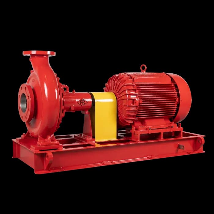
Electric System
Electric main pump, jockey pump and automatic controls.
For projects specifying an electric main pump. Available power and its requirements need to be assessed with the fire protection design.


Electric, diesel or combined sets with a jockey pump and project-specific controls. Send the required flow, pressure and specifications to define the configuration.
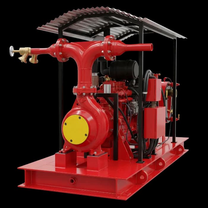
Compare the drive options and review each FBFS system. Selection starts with the hydraulic demand and infrastructure specified in the fire protection project.
Electric main pump, jockey pump and automatic controls.
For projects specifying an electric main pump. Available power and its requirements need to be assessed with the fire protection design.
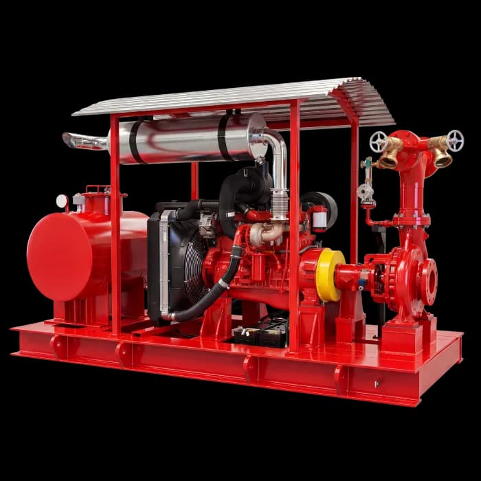
Diesel main pump, jockey pump and dedicated controller.
A diesel engine drives the main pump without relying on an electric motor. Fuel, starting, ventilation and exhaust are part of the assembly specification.
Electric pump, diesel pump and jockey pump in one project.
Combines electric and diesel drives where this arrangement is specified. Each pump’s duty, controls and supply are defined by the project.
Photographs of FB Bombas equipment. The final scope is defined in the technical proposal.
Series rating Fire Fighting Systems: 4.9/5 · 52 customer ratings
Consolidated figures supplied by FB Bombas from its customer ratings spreadsheet. The score and count refer to the series; they are not independent counts for each model or configuration.
Main pump, pressure maintenance, controls and integration work together. Review what needs to be specified before supply.
FBCN centrifugal pump assembly with an electric or diesel drive, selected for the project flow and pressure. Per the series manual, construction is back-pull-out, with a single-suction radial impeller.
Maintains network pressure and compensates for small losses, avoiding unnecessary starts of the main pump.
Pump controls, pressure readings and status signals. Functions and interfaces are defined for the specified arrangement.
Skid, piping, valves and connections organise the assembly. The layout needs to account for installation space and access.
| Component | Electric | Diesel | Electric + diesel |
|---|---|---|---|
| FBCN main pump | Included | Included | 2 pumps |
| Electric motor | Included | Not applicable | Included |
| Power supply | Included | Not applicable | Included |
| Diesel engine | Not applicable | Included | Included |
| Jockey pump | Included | Included | Included |
| Electric pump controller | Included | Not applicable | Included |
| Diesel engine controller | Not applicable | Included | Included |
| Pressure switches and sensing line | Included | Included | Included |
| Gauges and valves | Included | Included | Included |
| Starting batteries | Not applicable | Included | Included |
| Fuel tank | Not applicable | Included | Included |
| Cooling and air | Not applicable | Included | Included |
| Exhaust | Not applicable | Included | Included |
| Baseplate and coupling | Included | Included | Included |
Selection follows the points that NFPA 20 and the technical instructions of Brazilian fire departments require of the main pump, suction, driver and controls.
The largest demand of any system connected to the pump (hydrants, sprinklers, or their sum where the local rule requires it) must not exceed 150% of rated flow. Selection is made from the test curve of the pump, impeller diameter and speed combination, not from the catalog rated point: the curve must stay within the envelope checked at rated flow, at 150% of it and at shutoff.
Available NPSH is calculated at the reservoir’s minimum water level, and suction-flange pressure is checked at 150% of rated flow.
NFPA 20 accepts an electric pump connected to a reliable power source. Where the normal supply is not reliable, or in a high-rise building, it requires an alternate source, such as an on-site generator; a diesel standby pump that meets the same demand on its own removes that requirement. A diesel driver brings fuel, batteries, cooling, ventilation and exhaust into the design.
The jockey pump makes up small network losses, with start and stop pressures staggered with the main pump. In São Paulo, IT 22 requires a jockey pump when the hydrant or hose-reel network has more than six outlets, except with an elevated reservoir, limits its flow to 20 L/min and recommends about 10 m of water (100 kPa) between sequential pump starts.
Construction data for the centrifugal pump fitted to the FBFS, from the series manual, and the curve limits the project checks when it adopts NFPA 20.
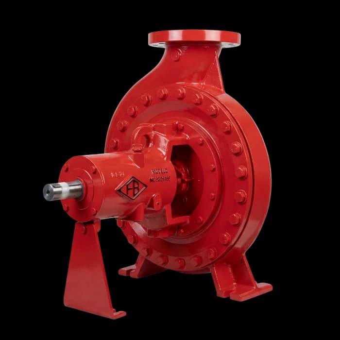
Series limits, which do not apply at the same time: the fire duty point comes from the curve selected for the project. In São Paulo, IT 22 does not recommend pumps above 100 m of water column (1 MPa) (C.1.13 and C.1.14).
Where the contract adopts NFPA 20, the centrifugal pump delivers at least 65% of rated pressure at 150% of rated flow, and shutoff is no more than 140% of rated pressure (6.2.1 and 6.2.2). For the field acceptance test, the annex lists shutoff, rated flow and 150% of rated flow as the important points (A.14.2.6.3). The chart shows limits, not the curve of a model.
Our archive shows fire pump assemblies and individual pumps. Each supply has its own scope, interfaces and project requirements.
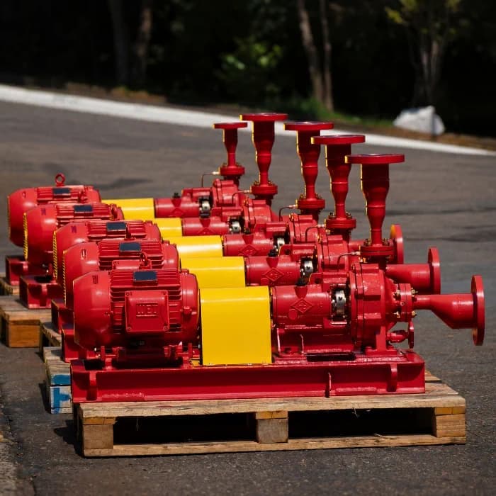
Consult the online catalogue and state the project standards. Supplied assembly documents should match the agreed configuration.
Configurations and technical references for the line.
View catalogueCentrifugal pump documentation. Also consult the motor and controller manuals for the supplied assembly.
View manualThe list for each supply is agreed in the proposal. Purchasing the assembly does not automatically approve the installation.
NFPA 20 and ABNT NBR 16704 address pumping assemblies. Sprinklers and hydrants have their own references, depending on the specified system. A design standard is not a product certificate.
A well-prepared enquiry helps assess the assembly, installation conditions and documentation required by your project.
Provide flow, pressure, suction conditions, building type, planned drive and required project standards.
Engineering reviews the pump, driver, controls and interfaces. Layout, power supply and installation conditions inform the proposal.
Agree on the assembly drawing, performance curve, test reports and manuals within the supply scope.
The package is assembled on its base according to the scope. The pump undergoes a bench performance test per ANSI/HI 14.6 and a hydrostatic test; a certified curve and FAT are supplied when the order requires them.
Answers to help compare configurations and prepare your technical enquiry.
The FBFS line combines a main centrifugal pump, electric or diesel drive, jockey pump, controllers, valves, instrumentation and base-mounted assembly. The project and technical proposal define the scope and interfaces of the package.
The electric configuration uses an electric motor for the main pump. The diesel configuration uses an internal combustion engine. The combined arrangement includes an electric pump and a diesel pump in the same project. Selection depends on hydraulic demand, available power and fire protection design requirements.
The jockey pump maintains network pressure and compensates for small losses. It avoids unnecessary main pump starts but does not replace the pump responsible for fire fighting demand. Selection needs to account for installation conditions.
Use the fire protection project demand, considering the served system, pipe network, suction conditions and pump duty point. An electric or diesel configuration does not have one fixed flow or pressure. Send these requirements to engineering for assembly selection.
No. They are standards for fire pumping assemblies. NFPA 20 addresses stationary pump selection and installation; ABNT NBR 16704 addresses pump assemblies for fire protection. The project should specify applicable requirements. Supply test reports and installation approval are separate documents.
This is defined by the fire protection design. Selection needs to account for the demand and rules applying to the specified systems: ABNT NBR 10897 for sprinklers and ABNT NBR 13714 for hydrants and hose reels, together with local requirements. Tell engineering which networks the system will serve.
Provide the configuration of interest, required flow and pressure, suction conditions, available drive and installation location. Include the specification, layout and required standards if available. You can start the enquiry with the information you have and complete it with the team.
Agree on the assembly drawing, performance curve, test reports and pump, driver and controller manuals in the proposal; FB defines deliverables per project, such as the data sheet, Q×H curve, dimensional drawing, FAT plan and bench test certificate. On the curve, check the envelope: at least 65% of rated pressure at 150% of rated flow and a shutoff of no more than 140% of rated pressure (Hydraulic Institute). For the field acceptance test, the NFPA 20 annex lists shutoff, rated flow and 150% of rated flow as the important test points, with speed and suction and discharge pressures recorded at each point (A.14.2.6.3). State the project, responsible engineer and local authority requirements before supply. Purchasing the assembly does not automatically approve the installation.
Send the current assembly identification and documents, required duty point, connections, available space and power supply conditions. Engineering assesses the new supply against the project and existing interfaces.
Provide project requirements, engine data and installation conditions. Fuel tank, starting system, ventilation and exhaust need to suit the assembly. Under NFPA 20, the tank holds at least 12 hours of engine run time, based on the manufacturer’s published fuel consumption, plus 5% of volume for expansion and 5% for sump (TIA 22-1, 11.4.1.3.1). In São Paulo, IT 22 requires fuel for the set to run at full load for at least twice the duration of the water supply, with a containment basin of one and a half times the tank volume; two battery sets, main and reserve, with a dual charger able to recharge a discharged battery within 24 hours; and a speed controller that holds rated speed within a 10% band (C.3.1.4, C.3.6, C.3.10 and C.3.11). Inspection and maintenance routines should follow equipment manuals and applicable requirements, rather than the configuration name alone.
FB Bombas has manufactured industrial pumps in Brazil since 1944 and has its factory in Cabreúva, São Paulo. Commercial enquiries can cover fire pump systems and their configurations, with documentation and supply scope defined for each project.
The public FBFS reference is an online configuration catalogue. The FBCN manual documents the centrifugal pump; it does not replace the specific driver, controller and supplied assembly documents. Contact the team for documentation corresponding to your project.
NFPA 20 chapter 6 covers overhung impeller centrifugal pumps, end-suction or in-line, and impeller between bearings pumps, with an axial or radial split case. These centrifugal pumps are not used where a static suction lift is required; that case calls for the vertical turbine pumps of chapter 7. In the FBFS, the main pump is from the FBCN series: a spiral casing cast in one piece, a single-suction radial impeller, back-pull-out construction, ANSI B16.1 125 or 250 lb flanges in cast iron, and packing or mechanical seal. The series runs from DN25 to DN300, with flow up to 2,200 m³/h and head up to 135 m (MTEC-03/00 manual, p.1, p.5 and p.7). These are series limits, not simultaneous; the fire duty point comes from the curve selected for the project.
In São Paulo, IT 22 sets the control logic: pressure switches start and stop the jockey pump automatically and only start the main pump (C.1.15.2); once started, the main or booster pump is stopped only manually, at its own panel in the pump room (C.1.6); and the pump reaches full speed in about 30 seconds (C.1.9). For the electric motor, the controller is selected by motor power in CV, starting is magnetic, acceleration does not exceed 10 seconds, and the panel comes with dimensional drawings, layout, wiring diagrams, terminal strip and bill of materials (C.2.17 and C.2.18). For diesel, a panel in the pump room shows pump running and automatic system off (C.3.9). The functions and interfaces of each FBFS panel are defined for the contracted arrangement.
Send the information you already have. Your selected configuration stays with the enquiry so our team can follow up in context.
Explore applications, installation or supply while keeping your fire protection project in context.