


FB Bombas Engineering Team7 min read
Installation covers foundation, alignment, preparation, startup and monitoring. On the FBEI, start-up is with valves open and suitable liquid inside (MAN001-10); the relief valve provides protection, not flow control. Confirm configuration and coupling procedures. Its alignment and temperature references are not universal limits for every FBE pump.
FB Bombas pump for this application
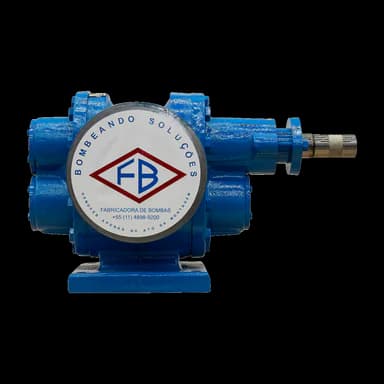
FBE Series
Installing and starting up an FBE?
In the FBE the shafts turn in bushing bearings (bronze, graphite or PTFE); a rolling bearing exists only in the optional external bearing housing.
Source: Manual FBE MTEC-01/01, Tabela 6; catálogo FBE 2026, p.3
At a glance
- FBE and FBEI gear pump installation follows a 5-step procedure: foundation, alignment, pre-operation, startup and monitoring.
- FBEI MAN001-10 cites radial alignment below 0.05 mm and angular alignment below 0.6°, referring to the coupling manufacturer.
- For FBEI, MAN001-10 limits the bearing support to 50 °C above ambient and 90 °C overall; confirm the configuration.
- Priming the pump before startup removes internal air and protects the gears against dry-running and premature wear.
- Start FBEI with suitable liquid inside and valves open; recheck alignment after installation and piping connection.
Limits and procedures must match the series, coupling and configuration actually supplied.
1. Read before installing — Pre-installation checklist
This checklist gathers checks from FBEI MAN001-10. Consult the manual for your series and the supply documents before installation; do not transfer filter, heating, sealing or alignment limits between FBE and FBEI.
- Install the pump as close as possible to the suction point
- The suction piping should have the fewest possible fittings and bends
- Suction piping diameter must be at least equal to the pump suction nozzle
- Install a 40 to 80 mesh strainer (depending on model) with the largest possible flow area to prevent cavitation
- After connecting piping, verify alignment between pump and driver. Rotate the shaft manually at least one full turn
- Suction and discharge piping must be properly supported and aligned with nozzles — no pipe stress on the pump
- Do not overtighten flange bolts. Use flexible connections whenever possible
- Never use the relief valve for pressure or flow control. The relief valve protection cap must face the suction side
- Verify that the relief valve opening pressure is correctly adjusted
- For pumps without relief valve, install line protection: valve, pressure switch, torque limiter, etc.
- Install a permanent strainer before any test or startup. If not possible, use a temporary witch-hat type strainer
- For pumps with heating jacket: maximum steam 185 °C and/or 10 bar; maximum thermal fluid 232 °C and/or 10 bar
- Ensure the mechanical seal is correctly adjusted with all accessories and auxiliary fluids installed and connected
- Verify that all operating conditions match those specified in the pump data sheets and certified documents
Warning
Operating the pump with fluids other than specified, or under conditions outside the original sizing, without written authorization from FB Bombas, voids the warranty. Damage from operation and maintenance failures may completely void the warranty.
2. Foundation and leveling
Before installing, make sure the floor and beams support the full load of the foundation plus the pump. Follow the base housing dimensions per the assembly drawing.
After pouring the concrete, level the assembly. Place the unit on the foundation using shim plates between the base and foundation. Do not tighten anchor bolts yet. With the base level, proceed to align the suction and discharge flanges with the piping.
Grouting fills the space between the foundation and the pump base with self-leveling grout. Build a form around the foundation. When the grout cures, make piping connections and recheck alignment.
3. Pump-motor alignment
Correct pump-motor alignment is one of the most important aspects of installation. Misaligned machines cause vibration, premature component wear and mechanical seal failure. Pumps leave the factory pre-aligned, but shipping and handling will misalign the assembly.
Use a dial indicator or laser for alignment. If unavailable, use a straight edge (parallel alignment, longitudinal direction) and feeler gauge (angular alignment, axial direction). Follow the coupling manufacturer recommended gap.
Engineering note
Alignment tolerances (MAN001-10, p. 15): radial less than 0.05 mm, angular less than 0.6°. Flexible couplings accommodate small deviations during operation, but this does NOT replace correct alignment at installation.
4. Pre-operation actions
With the foundation cured, piping connected and alignment verified, execute the following sequence before the first startup:
- Secure the pump and driver firmly to the base
- Secure suction and discharge piping
- Connect auxiliary piping and connections (if applicable)
- Make electrical connections. Ensure all motor protection systems are adjusted and working
- Verify driver rotation direction with pump uncoupled — avoid dry-running
- Ensure the rotating assembly turns freely by hand
- Verify alignment per the procedure in the previous section
- Install the coupling guard
- Prime with the specified liquid and remove air, following the sealing procedure. The FBEI must not run with water or without liquid (MAN001-10).
- Ensure packing gland nuts are only finger-tight (packed pumps)
- Check that suction and discharge are open and unobstructed before starting. Confirm that overpressure protection is correctly set.
5. Startup and monitoring during operation
With the pre-operation checklist completed, proceed to startup. Monitor the parameters below continuously during the first hours of operation:
- Keep the discharge path open. Set duty using the approved speed and control arrangement; do not throttle discharge or use the relief valve for continuous control.
- Monitor motor current and voltage, comparing each quantity with its nameplate rating and protection settings.
- Verify that suction pressure matches the design
- Ensure the pump operates free from abnormal vibration and noise
- Monitor the bearing support according to the configuration’s manual. FBEI MAN001-10 cites up to 50 °C above ambient, without exceeding 90 °C overall.
Engineering note
Packing (MAN001-10, p. 13): adjust by tightening gland nuts approximately 1/6 turn. During the first 5 to 8 hours, dripping is normal — this is the break-in period. After stabilization, weekly checks are sufficient. During the first 2 hours, check every 15 minutes.
6. Shipping and storage
Shipping must follow applicable safety standards. Never use a single lift eye (on the motor or pump) to lift the complete assembly. Use proper rigging devices rated for the total weight.
For storage: keep free from moisture, dust, vapors and salinity. Remove packing before storage. Clean mechanical seals dry, without liquids. Wrap in waterproof material. Plug all connections (suction, discharge, drains, pressure taps).
Note
Pumps awaiting operation: rotate the assembly manually every 15 days. Pumps stored for more than 1 year: reconserve every 12 months (disassemble, clean, reapply preservation).
7. Recommended spare parts (2-year kit)
FB Bombas Engineering recommends stocking the following FBEI spare parts kit for 2 years of operation (MAN001-10):
- Internal gear
- Pin
- Support and internal gear bushing
- Sealing kit: packing set or mechanical seal + bearing
Key point
Request spares using the model, serial number and equipment drawing. Confirm items, materials and delivery lead time; the reference kit does not replace the configuration’s parts list.
8. Note on confined spaces and high temperatures
Confined-space and explosive-atmosphere measures depend on risk assessment, area classification and applicable installation rules. Changing the guard material alone does not resolve that assessment. Confirm access, ventilation, electrical equipment and procedures with those responsible for design and operation.
For high-temperature pumps: install a ventilation system and monitor pressure gauge and thermometer periodically.