

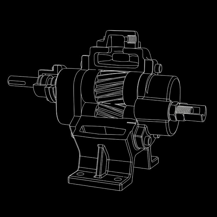
Sizing a gear pump requires three calculations in sequence: actual flow (Q = volumetric displacement × speed × volumetric efficiency), the differential pressure imposed by the circuit (discharge minus suction, including pipe friction loss at the operating viscosity) and shaft power (P = Q × Δp ÷ 600 ÷ overall efficiency, with Q in L/min and Δp in bar). Fluid viscosity limits the allowable speed and increases the required power — which is why sizing always starts from the fluid, never from the model.
At a glance
- Gear pump sizing is three calculations in sequence: flow from volumetric displacement, differential pressure from the circuit and shaft power with motor reserve.
- Theoretical flow is Q = Vg × n ÷ 1000 (L/min); actual flow subtracts internal slip, which grows with pressure and decreases with viscosity.
- Hydraulic power in kW is Q × Δp ÷ 600 (Q in L/min, Δp in bar); shaft power divides that value by overall efficiency and the motor carries a reserve above it.
- The order never reverses: the fluid defines the allowable speed, the speed defines the pump size and the circuit defines the motor power.
- Send the checklist data; confirm selection and performance documentation with engineering.
1. What sizing a gear pump actually means
Sizing a gear pump means finding the combination of volumetric displacement, speed and motor that delivers the flow the process requires against the pressure the circuit imposes — with the real fluid, at the real operating viscosity and temperature. The calculation order matters: first the fluid sets the limits (allowable speed, maximum pressure), then flow sets the size, and finally pressure sets the power.
This walkthrough follows the rotary positive displacement pump terminology of ANSI/HI 3.1-3.5, from the Hydraulic Institute, and the application data of the FBE series technical manual. It complements — not replaces — selection by viscosity: here the focus is the calculation; there, the model tables by viscosity range.
| Process data | Typical unit | What it defines in the calculation |
|---|---|---|
| Fluid and viscosity at operating temperature | SSU or cSt | Allowable speed, drive type, friction power |
| Flow required by the process | L/min or m³/h | Volumetric displacement (pump size) |
| Discharge pressure + line friction loss | bar or kgf/cm² | Differential pressure Δp and shaft power |
| Suction condition (lift, length, temperature) | m, mca | Available NPSH and cavitation risk |
| Duty cycle (continuous/intermittent) | — | Power reserve and motor class |
2. Step 1 — Flow: from volumetric displacement to actual flow
A gear pump displaces a fixed volume per revolution — the volumetric displacement Vg, expressed in cm³/rev in the datasheet. Theoretical flow is therefore proportional to speed: double the speed, double the flow. This is the fundamental difference from a centrifugal pump, where flow and pressure are coupled on the same curve.
Actual flow is lower than theoretical because of internal slip: fluid backflow through the clearances between gears, casing and covers, from discharge back to suction. Slip grows with differential pressure and decreases with viscosity — with viscous fluids, the clearances seal themselves. The ratio of actual to theoretical flow is the volumetric efficiency ηv, and each model’s value at each condition comes from the manufacturer performance curve.
Q_teorica = (Vg × n) / 1000
Q_real = Q_teorica × ηv
Theoretical and actual flow (Q in L/min; Vg in cm³/rev; n in rpm)
Speed n is not free: it is limited by viscosity. Before calculating flow, confirm the allowable speed for your fluid in the manual’s viscosity × speed table — sizing at 1750 rpm a fluid that requires 500 rpm overestimates flow by more than 3 times.
3. Step 2 — Differential pressure: what the circuit actually imposes
Differential pressure is discharge pressure minus suction pressure at the calculation’s defined reference points. Assess elevation, tank pressures and line losses. For laminar Newtonian flow, loss increases with viscosity, so both cold starting and normal duty must be checked.
Check the result against configuration limits: differential pressure, maximum inlet pressure and discharge pressure are distinct quantities. FBE manual Table 5 labels its pressure row as maximum inlet pressure; do not use it as a differential-pressure-versus-viscosity curve. Also confirm relief protection against blocked discharge.
Δp = p_descarga − p_succao
p_descarga = p_destino + Δp_atrito(linha, viscosidade) + Δp_estatico(elevacao)
Differential pressure from the circuit
A relief valve is not optional on a positive displacement pump. Without it, a closed discharge valve drives the system to motor stall pressure or mechanical failure — rotary pump application standard (ANSI/HI 3.1-3.5).
4. Step 3 — Power: hydraulic, shaft and motor reserve
Hydraulic power is the product of flow × differential pressure. In everyday units — Q in L/min and Δp in bar — the conversion constant is 600: P(kW) = Q × Δp ÷ 600. That is the power delivered to the fluid; shaft power is higher, because part of the work is lost to internal friction (viscous and mechanical) and slip. The ratio between the two is the overall efficiency η.
With viscous fluids, the viscous friction share grows and dominates: the same pump, at the same flow and pressure point, demands more power with asphalt than with diesel. That is why the final power does not come from a generic formula — it comes from the model performance curve at the operating viscosity, and the FBE manual tabulates the recommended power reserve over the calculated value, larger for small motors (which have less thermal margin) and smaller for large ones.
P_hidraulica (kW) = (Q × Δp) / 600
P_eixo = P_hidraulica / η
T (N·m) = (Vg × Δp) / (20 × π × η_mec)
Hydraulic power, shaft power and torque (Q in L/min; Δp in bar; Vg in cm³/rev)
5. Worked numerical example: lube oil at 60 L/min and 8 bar
Worked example: oil at 40 °C with assumed viscosity of 1,000 SSU, 60 L/min flow and 8 bar differential pressure. FBE manual Table 2 lists 1,150 rpm in that band for the specified sizes. Speed and model still require confirmation for the complete duty.
Adopting, for the example, a volumetric efficiency of 0.90 at this condition (the real value comes from the model curve): the required theoretical flow is 60 ÷ 0.90 = 66.7 L/min. The minimum volumetric displacement is Vg = 66.7 × 1000 ÷ 1150 = 58 cm³/rev — the chosen model is the catalog one with Vg immediately above.
Hydraulic power is 60 × 8 ÷ 600 = 0.80 kW; with an overall efficiency of 0.60 in the example, shaft power is 1.33 kW. With the manual’s reserve for motors in this range, the next commercial motor size closes the selection — subject to confirmation with the model’s certified curve.
- Speed from viscosity: 1,000 SSU → 1150 rpm (direct drive, 6 poles)
- Theoretical flow: 60 ÷ 0.90 = 66.7 L/min → minimum Vg = 58 cm³/rev
- Power: P_hyd = 0.80 kW → P_shaft = 1.33 kW → next commercial motor size, with manual reserve
- Final checks: configuration pressure limits, suction conditions, starting power and relief protection.
6. The four errors that most often compromise sizing
Review these four points before selecting the pump and motor:
- Datasheet viscosity instead of operating viscosity: the cold fluid at start-up can be several times more viscous than at steady-state temperature — start-up power and friction loss must be checked at the worst condition, not the nominal one.
- Speed above the allowable for the viscosity: catalog flow at the wrong speed causes suction cavitation and accelerated wear of bushings and gears.
- Motor without reserve over the calculated power: viscosity variations, pressure variations and start-up itself consume the margin — the reserve tabulated in the manual is not conservatism, it is real transient behavior.
- Suction treated as a detail: a long, narrow inlet line with a viscous fluid destroys available NPSH — suction sizing is as decisive as discharge sizing.
Golden rule of positive displacement pump sizing: the fluid defines the speed, the speed defines the size, the circuit defines the power — never in the reverse order.
7. Checklist: the 7 data points that close the sizing
Send the data below for a selection assessment. Engineering may request further information and confirm model, speed, motor and documentation in the proposal. The numerical example is neither a certified curve nor supply approval.
- Pumped fluid (trade name and concentration, if a solution)
- Viscosity at operating temperature (SSU or cSt)
- Working temperature — minimum and maximum
- Flow required by the process (L/min or m³/h)
- Discharge pressure — or line layout (diameter, length, elevation, fittings)
- Suction condition: lift or flooded suction, line length
- Duty cycle: continuous or intermittent, starts per day