


FB Bombas Engineering Team15 min read
Calculate available NPSH (NPSHa) for the most demanding suction conditions, including cold start, when the oil is most viscous, and compare it with the inlet requirement stated for the pump, speed, liquid and viscosity. For an open tank with negligible surface velocity: NPSHa = Patm/γ + Hs − Hf − Pv/γ.
Set an application-specific margin; FB Bombas does not publish one NPSHr or a universal margin for the FBE range (MTEC-01/01).
FB Bombas pump for this application
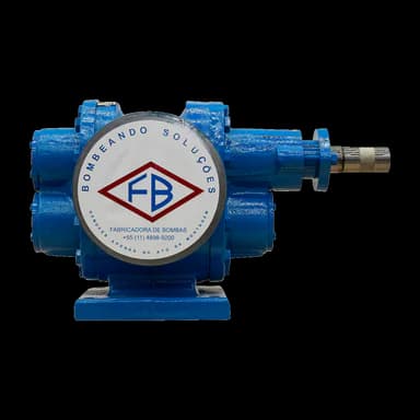
FBE Series
Is the suction of your gear pump critical?
The FBE is the FB Bombas external gear pump for oils, asphalt and viscous chemicals: Table 2 of the manual covers from 2,500 SSU (1/8″ to 1/4″) to 100,000 SSU (3″ to 6″), and models from 1/8″ to 4″ are in stock, with availability confirmed in the quotation.
Source: Manual FBE MTEC-01/01, Tabela 2
At a glance
- NPSHa describes available absolute suction head above the liquid’s vapour pressure.
- Compare NPSHa with the configuration’s inlet requirement and the process-specific margin.
- Calculate losses using viscosity and flow regime at duty and startup.
- The example sums hypothetical inputs to obtain 9.7 m; it is not an FBE test.
- Provide tank level, suction piping and fluid properties to assess FBE selection.
1. What is NPSH and why it matters
This article covers NPSH for gear pumps with viscous liquids: the inlet requirement is NPIPR, viscosity weighs on the calculation and cold start is usually the worst condition.
For the general definition of NPSH, NPSHa vs NPSHr and how to read a centrifugal pump curve, see the article on NPSH in centrifugal pumps; to calculate the installation NPSHa, use the NPSH calculator.
NPSH stands for net positive suction head: the absolute suction head, in metres of the liquid itself, left above vapour pressure at the pump datum. The Hydraulic Institute (HI) defines cavitation as the formation of vapour cavities in a flowing liquid where pressure falls below the liquid’s vapour pressure, followed by rapid collapse of those cavities as pressure rises downstream.
In an external gear pump, the 2026 FBE catalogue (p.2) describes the principle: gear meshing creates a depression in the suction chamber, and fluid flows from the tank to fill the cavities between the teeth and the casing. That chamber is where absolute pressure must stay above the liquid’s vapour pressure under every operating condition.
Gear pumps also require suction checks. For viscous liquids, the Hydraulic Institute identifies viscosity as a factor affecting net positive inlet pressure required (NPIPR). Noise, vibration and reduced flow have several possible causes; compare inlet conditions with configuration-specific data rather than assuming every positive displacement pump is more tolerant of cavitation.
In its text on viscosity (How Viscosity Affects Pumping), HI shows the other side: in positive displacement pumps, higher viscosity reduces internal slip and increases volumetric efficiency, but it also raises input power and NPIPR. HI notes that these generalities are not absolute, that specific designs change capabilities significantly and that the manufacturer should be consulted for specific recommendations.
| Question | Centrifugal pump (FBCN) | Gear pump (FBE and FBEI) |
|---|---|---|
| Which term the manufacturer states | NPSHr, read on the model curve; the tested NPSH3 is the reference | NPIPR, the HI term for positive displacement, stated as pressure; FB Bombas does not publish a single NPSHr for the FBE (MTEC-01/01) |
| What raises the requirement | Flow: NPSHr rises along the curve | Viscosity: HI shows that NPIPR rises with it |
| Critical condition | High flow, on the right of the curve, and temperature above design (DOE/HI) | Cold start, with the oil at its most viscous, minimum tank level and the suction strainer |
| FB Bombas data to check against | FBCN curves with NPSHr and manual MTEC-03/00 | Table 2 of manual MTEC-01/01 (speed by viscosity range) and the 2026 FBE catalogue |
Engineering note
The suction margin must account for cold starting, minimum tank level, maximum temperature, filters and process variation. Ask engineering for the proposed configuration’s inlet requirement. ANSI/HI 9.6.1 guidance for rotodynamic pumps is not an FBE NPSHr table.
2. NPSHa, NPSHr, NPSH3 and NPIPR: what each term means
The NPSHa, NPSHr and NPSH3 definitions follow the Hydraulic Institute table of definitions; NPIPR comes from HI’s text on viscosity. The distinction matters because NPSHa belongs to the installation, whereas NPSHr belongs to the pump under a stated condition, as the table shows. An NPSHr stated for another speed, flow or liquid does not describe the new condition.
To compare a requirement given as pressure with NPSHa in metres, convert with p = ρ·g·h, using the liquid’s density at the evaluated condition. For an oil of 940 kg/m³, for example, 1 kgf/cm² (98,066.5 Pa) corresponds to 98,066.5 ÷ (940 × 9.80665) ≈ 10.6 m of liquid.
| Term | Definition | Where it comes from |
|---|---|---|
| NPSHa | Total suction head of liquid absolute at the NPSH datum, less the liquid’s absolute vapour pressure head; for a reciprocating pump, acceleration head loss is also subtracted. | The installation: levels, pressures, piping and liquid. |
| NPSHr | Minimum NPSH given by the manufacturer for a specified performance at the specified flow, speed and liquid. | The manufacturer, for each stated condition. |
| NPSH3 | NPSHr value at which first-stage head drops by 3% due to cavitation. | Tests on centrifugal (rotodynamic) pumps. |
| NPIPR | Net positive inlet pressure required, the term HI uses for positive displacement pumps; as it is stated as a pressure, compare it with NPSHa by converting with p = ρ·g·h. | The manufacturer; HI shows it increases with viscosity. |
3. Available NPSH (NPSHa): the formula
Available NPSH is a property of the installation. The expression below assumes an open tank with negligible surface velocity; Hs is positive when the surface is above the pump datum and negative when below. For a closed tank, replace Patm with the absolute pressure above the liquid. Use absolute pressures and the liquid’s specific weight γ.
NPSHa = (Patm / γ) ± Hs − Hf − (Pv / γ)NPSHa canonical formula
4. The formula variables, explained
Each term of the equation has direct physical meaning and consistent units in metres of liquid column (m.l.c.). Working in m.l.c. is more intuitive than in bar or kgf/cm² because it allows direct comparison between different fluids.
The atmospheric term is the site’s absolute pressure divided by the liquid’s specific weight. At the standard atmosphere of 101,325 Pa, an oil of 940 kg/m³ has Patm/γ = 101,325 ÷ (940 × 9.80665) ≈ 11.0 m, the value used in the example in section 6.
With water at 20 °C (998.16 kg/m³, NIST), the same pressure supports about 10.35 m.
Two terms change with the site and the process. Atmospheric pressure falls with altitude: the 1976 U.S. Standard Atmosphere gives 89.88 kPa at 1,000 m, about 9.75 m of the same oil, 1.24 m less than at sea level.
Vapour pressure rises with temperature: for water, it goes from 2.34 kPa at 20 °C to 47.4 kPa at 80 °C (NIST), from about 0.24 m to 4.98 m of column.
| Symbol | Name | Description |
|---|---|---|
| Patm / γ | Local atmospheric pressure | Use atmospheric pressure measured or calculated for the site, divided by the liquid’s specific weight. Do not apply a fixed linear reduction with altitude. |
| ± Hs | Geometric suction height | Positive (+) if pump is below liquid level (flooded suction). Negative (−) if pump is above (lift suction). |
| Hf | Suction friction loss | Losses in suction pipes, bends, valves, filters and fittings. They depend on flow, geometry, roughness and flow regime; the relationship is not always quadratic. |
| Pv / γ | Fluid vapour pressure | Vapour pressure at the evaluated temperature, divided by the liquid’s specific weight. Obtain it from reliable thermophysical data or the fluid datasheet, keeping units consistent. |
5. The hidden impact of viscosity on NPSHa
With a viscous liquid, the focus is friction loss (Hf). The Hydraulic Institute computes the loss for incompressible flow of any fluid in any pipe with the Darcy-Weisbach equation: hf = f·(L/D)·v²/(2g).
The friction factor f depends on the Reynolds number, Re = v·D/ν, and kinematic viscosity ν sits in the denominator: the more viscous the liquid, the lower the Reynolds number.
HI separates three ranges. Below Re 2,000, flow is laminar and the friction factor is f = 64/Re for any fluid in any pipe, with no roughness term. Above 4,000, flow is usually turbulent and f comes from the Moody diagram.
Between 2,000 and 4,000 lies the critical zone, where flow may be highly unstable and the friction factor is indeterminate.
Substituting f = 64/Re into the equation, the loss in a straight laminar run becomes hf = 32·ν·L·v/(g·D²). Two consequences follow directly. The loss is proportional to kinematic viscosity: twice the viscosity gives twice the loss. And, at fixed flow, velocity falls with the square of the diameter, so the loss falls with its fourth power.
There is no single oil-to-water friction-loss multiplier. In the same pipe, the ratio depends on flow, diameter and each liquid’s flow regime. Use product viscosity at the evaluated temperature and recalculate suction losses, including startup conditions.
Warning
Check the fluid and temperature underlying a friction-loss table. For a different liquid, recalculate with the appropriate density, viscosity and flow regime. Assess both duty and startup instead of transferring water data directly to viscous oil.
6. Worked example: an oil suction balance
This example illustrates only the addition of NPSHa terms. It is not a measured installation or an FBE pump selection. The hypothetical inputs, already expressed in metres of liquid, are 11.0 m atmospheric pressure head, a level 1.5 m above the pump datum and 2.8 m suction losses.
Vapour pressure head is neglected only for this illustrative calculation. Actual design requires measured or documented pressure, density, viscosity and vapour pressure; Hf is calculated from flow, internal diameter, pipe lengths and fittings.
- Patm/γ = 11.0 m of liquid (standard atmosphere, 940 kg/m³ oil; see section 4)
- + Hs = +1.5 m (flooded suction)
- − Hf = −2.8 m (assumed loss; not calculated in this example)
- − Pv / γ ≈ 0 m
- NPSHa = 11.0 + 1.5 − 2.8 − 0 = 9.7 m of oil
7. Calculated Hf: the same suction at duty and at cold start
In section 6, the 2.8 m loss was assumed. Here we calculate the loss for a line that is also hypothetical: 15 m of straight suction pipe with an 80 mm internal diameter, a flow of 10 m³/h and an oil at 1,000 SSU at operating temperature and 5,000 SSU at cold start.
Using the approximate conversion in the 2026 FBE catalogue (p.5), valid above 300 SSU (cSt = SSU ÷ 4.635), that gives about 216 and 1,079 cSt.
The HI units table gives close values for the same viscosities, 220 and 1,100 cSt. With them, the losses rise by up to about 0.09 m and the rounded NPSHa results stay the same.
Suction velocity is v = Q/A ≈ 0.553 m/s. At duty, Re = v·D/ν ≈ 205; at startup, ≈ 41. Both are far below 2,000, so flow is laminar in both cases, with f = 64/Re ≈ 0.312 and ≈ 1.56.
The table summarises the straight run, without bends, valves or filter, and adds the same calculation for a 100 mm pipe and, as a reference, for water.
With water at 20 °C (≈ 1.0 cSt, NIST), the same line runs in turbulent flow, with Re ≈ 44,000. For new, clean commercial steel (0.0457 mm roughness, HI table) and HI’s explicit equation, f ≈ 0.023 and the loss is about 0.07 m.
The oil loses about 13 times that at duty and 67 times cold: there is no single multiplier.
Taking the oil losses to the section 6 balance, with the other terms unchanged (11.0 m atmospheric pressure head, level 1.5 m above the datum and negligible vapour pressure), NPSHa is about 11.6 m at duty and 7.9 m at cold start.
With the tank 3.0 m below the datum at startup, what remains is 11.0 − 3.0 − 4.56 ≈ 3.4 m.
The 100 mm pipe cuts the startup loss to about 1.87 m and brings NPSHa back to roughly 10.6 m with the level 1.5 m above. The ratio between the losses, (80/100)⁴ ≈ 0.41, is the fourth power the laminar formula predicts.
Bends, valves and the filter, especially when dirty, add losses of their own: the straight run is a lower bound on the loss, not the total.
Scroll the table to see every column. The first column stays on the left.
| Condition | Viscosity | Re | f (friction factor) | Hf |
|---|---|---|---|---|
| Duty, 80 mm pipe | 1,000 SSU ≈ 216 cSt | ≈ 205 | ≈ 0.312 | ≈ 0.91 m |
| Cold start, 80 mm pipe | 5,000 SSU ≈ 1,079 cSt | ≈ 41 | ≈ 1.56 | ≈ 4.56 m |
| Duty, 100 mm pipe | 1,000 SSU ≈ 216 cSt | ≈ 164 | ≈ 0.390 | ≈ 0.37 m |
| Cold start, 100 mm pipe | 5,000 SSU ≈ 1,079 cSt | ≈ 33 | ≈ 1.95 | ≈ 1.87 m |
| Water at 20 °C, 80 mm pipe (reference) | ≈ 1.0 cSt (NIST) | ≈ 44,000 | ≈ 0.023 | ≈ 0.07 m |
Engineering note
The figures in this section are illustrative: they show the order of magnitude of a cold start, not a pump selection. Density also changes with temperature and was held constant to isolate the effect of viscosity. For design, use the product’s measured viscosity at the lowest expected temperature, the actual length and every fitting in the line.
8. Final check: NPSHa vs NPSHr
The section 6 example gives NPSHa = 9.7 m of liquid. To assess an FBE configuration, obtain its inlet requirement at the duty speed, flow and viscosity and define the appropriate margin. Request this information for the selected configuration together with the assessment conditions.
Changing only the level to Hs = −3.0 m gives 11.0 − 3.0 − 2.8 = 5.2 m in this hypothetical balance. The 4.5 m difference shows the effect of tank level. Neither result alone proves cavitation-free operation or approves the installation.
The worst case is not always a single one. Cold start maximises viscosity and friction loss; maximum temperature maximises vapour pressure; minimum tank level reduces Hs. Check every combination the process allows and compare it with the inlet requirement stated for that condition, in metres or in pressure, converting with the liquid’s density.
Among the FB Bombas series, the 2026 FBEI catalogue (p.4) describes the standard series as driven by gear reducers at low speeds, which, according to the catalogue, gives a low required NPSH.
For the FBE, the 2026 catalogue (p.5) recommends lower speeds as viscosity rises: 1,750 rpm with direct drive from 30 to 250 SSU, on the 1/8″ to 1″D models, and 300 to 150 rpm, with pulley or reducer, from 50,000 to 100,000 SSU, on the 3″ to 6″ models. Neither catalogue publishes a numerical NPSHr.
9. Cavitation prevention checklist
Collect these suction data and checks before requesting pump selection:
- Install the pump as close as possible to the suction point, as FB Bombas Engineering requires for the FBEI (MAN001-10), and, where the layout allows, below the liquid level (flooded suction), which makes Hs positive.
- Use suction piping with a diameter at least equal to the pump’s suction port (MAN001-10); in laminar flow, the loss falls with the fourth power of the diameter.
- Design the suction line with as few fittings as possible (MAN001-10) and account for losses in bends, reducers, valves and filters, including the dirty-filter condition expected in the design.
- Wherever possible, fit a filter with the mesh specified for the model (MAN001-10 gives 40 to 80 mesh for the FBEI) and the largest possible open area, which the FBEI links to avoiding cavitation (MAN001-10); without a permanent filter, use a temporary witch’s-hat strainer before any test or startup.
- Calculate friction loss with viscosity at the minimum operating temperature (cold start), not only at the nominal one; in the section 7 example, it rose from 0.91 m to 4.56 m.
- With hot fluids, check vapour pressure at the maximum process temperature: the closer to vaporisation, the larger the Pv/γ term and the lower the NPSHa.
- Install a suction gauge with a low-pressure scale, including vacuum. During operation, MAN001-10 asks you to check that suction pressure matches the design value and that the pump runs free of abnormal vibration and noise.
- If NPSHa is tight, increase the diameter, shorten the line, remove fittings, lower the pump or warm the product before startup where the process allows; the configuration’s speed is also part of the assessment with the manufacturer.
10. Practical conclusion
Sizing NPSH for a gear pump does not take sophisticated maths, but it does take the actual viscosity at the actual temperature, including at startup. In this article’s example, the same line lost 0.91 m at duty and 4.56 m cold, and moving from 80 to 100 mm recovered about 2.7 m of NPSHa at cold start.
If your application involves diesel oil, BPF fuel oil, asphalt, resins, paints, molasses or glucose, FB Bombas application engineering in Cabreúva, Brazil, reviews NPSHa with your installation data and recommends the right series and configuration. Send the fluid, its viscosity at minimum and operating temperatures, the tank level and the suction layout with diameters, lengths and fittings.