


FB Bombas Engineering Team7 min read
For FBE, match viscosity at operating temperature with model and speed. Per Table 2 (MTEC-01/01), speed is 1,750 rpm for 30–250 SSU, 1,150 rpm for 250–2,500 SSU and 850 rpm for 2,500–7,500 SSU, only for the listed sizes; higher ranges use pulleys or a gearbox. Also confirm differential pressure, suction, materials and power. The catalogue’s 22 kgf/cm² is a range maximum, not every configuration’s rating.
FB pump for this application
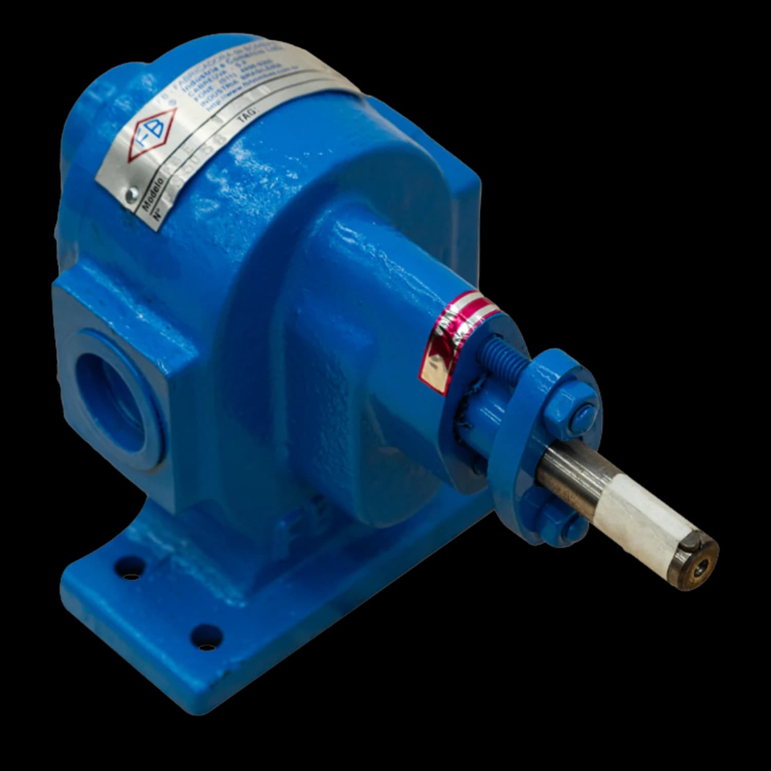
FBE Series
Does your fluid reach 7,500 SSU?
The FBE 1″ covers fluids up to 7,500 SSU and is among the 1/8″ to 4″ models in stock, with availability confirmed in the quotation.
Source: Manual FBE MTEC-01/01, Tabela 2
At a glance
- Viscosity guides speed and drive; pressure limits require configuration-specific verification.
- The FBE series operates from 30 to 100,000 SSU (limit per size, Table 2 of MTEC-01/01), serving everything from light oils to CAP asphalt in industrial processes.
- Each viscosity band (MTEC-01/01) has specific sizes and speeds; above 7,500 SSU, the table specifies pulleys or a gearbox.
- The current catalogue broadens the FBE overview; confirm temperature, connection, material and sealing for supply.
- FB Bombas matches the process fluid's viscosity curve to the FBE speed on every selection, derating the 1750 rpm drive as the SSU rating demands.
Compare the tables with the current catalogue and proposed configuration.
1. Why viscosity determines pump selection
Viscosity guides speed, drive selection and assessment of internal and suction losses. Allowable pressure also depends on configuration, material and temperature; it must not be inferred from viscosity alone.
More viscous fluids require lower speed to preserve volumetric efficiency and the service life of internal components (gears and bushings). The FB Bombas FBE series operates with viscosities from 30 to 100,000 SSU (limit per size — Table 2, MTEC-01/01), covering everything from light oils to CAP asphalt.
Engineering note
Table 2 reduces speed in higher-viscosity bands. Check the sizes included in each row and validate inlet pressure and differential pressure separately.
2. Selection table: viscosity × speed × drive type
The table below reproduces Table 2 of MTEC-01/01, in which FB Bombas Engineering defines the speed and transmission type for each viscosity range, as well as the available FBE models.
Scroll the table to see every column. The first column stays on the left.
| Viscosity (SSU) | Speed (rpm) | Transmission | Available models |
|---|---|---|---|
| 30 to 250 | 1750 | Direct | 1/8″, 1/4″, 1/2″, 3/4″, 1″ and 1″D |
| 250 to 2,500 | 1150 | Direct | 1/8″, 1/4″, 1/2″, 3/4″, 1″, 1″D, 1½″, 2″, 3″, 4″ and 5″ |
| 2,500 to 7,500 | 850 | Direct | 1/2" to 1"D, 1.1/2" to 6" |
| 7,500 to 10,000 | 700 to 500 | Pulley or gearbox | 1.1/2" to 6" |
| 10,000 to 50,000 | 500 to 300 | Pulley or gearbox | 1.1/2" to 6" |
| 50,000 to 100,000 | 300 to 150 | Pulley or gearbox | 3" to 6" |
3. Inlet pressure and differential pressure: separate quantities
MTEC-01/01 Table 5 labels the pressure values below as maximum inlet pressure. They are not an allowable differential-pressure curve. The current catalogue states up to 22 kgf/cm² for the range; selection must confirm inlet, differential and discharge pressure for the model, material and temperature.
Scroll the table to see every column. The first column stays on the left.
| Size | Maximum inlet pressure (kgf/cm²) | Max. speed (rpm) | Gears |
|---|---|---|---|
| 1/8″ to 1″ (incl. 1″ D and 1″ DA) | 22 | 1,750 | 2 helical |
| 1.1/2″ and 2″ (incl. 2″ A) | 14 | 1,150 | 2 helical (1½″); 4 double-helical (2″) |
| 3″ | 12 | 1,150 | 4 double-helical |
| 3″ M9 · 4″ M6 · 4″ M8 | 8 | 1,150 | 4 double-helical |
| 4″ M12 | 6 | 1,150 | 4 double-helical |
| 5″ and 6″ (Table 1) | Confirm — not listed in Table 5 | 1,150 (5″) · 500 (6″) | see manual |
Warning
Table 2 addresses viscosity and speed by size; Table 5 covers construction data. The reviewed viscosity rows do not list 3/8″, so that configuration requires confirmation.
4. Motor power reserve
FB Bombas Engineering adopts specific power reserves for electric motor selection (MTEC-01/01, Table 4). This reserve protects the motor against load peaks during startup, viscosity variations or off-design conditions.
| Required power | Power reserve |
|---|---|
| Up to 2 hp | 50% |
| 3 to 5 hp | 30% |
| 6 to 10 hp | 25% |
| 11 to 25 hp | 15% |
| Above 25 hp | 10% |
5. FBE model nomenclature
The FBE series has variants that extend the flow and pressure range for specific applications. The letters after the diameter indicate the construction configuration per FB Bombas Engineering (MTEC-01/01):
- A — Larger diameter gear (higher flow in the same body)
- CA — With heating jacket (for fluids that solidify at ambient temperature, such as asphalt)
- D — Longer gear (higher flow per revolution)
- DA — Longer gear with larger module (maximum flow)
- M6 — Module 6 gear
- M8 — Module 8 gear
- M9 — Module 9 gear
- M12 — configuration code; module 11 appears in MTEC-01/01. Confirm the drawing before specifying parts.
6. Available construction materials
The FBE series is manufactured in five material options per Table 6 (MTEC-01/01). The choice depends on chemical compatibility with the fluid, operating temperature and corrosion resistance requirements.
- Cast iron — ASTM A48 CL30 casing; confirm compatibility and configuration limits at design temperature.
- Ductile iron — ASTM A536 60-40-18 casing; confirm compatibility and configuration limits at design pressure and temperature.
- Carbon steel — ASTM A216 WCB casing; confirm compatibility and configuration limits at design temperature.
- Stainless steel — ASTM A743 CF8M casing; selection depends on fluid composition, concentration and temperature.
- Bronze — ASTM B584 C93700 (SAE J462 64) casing; duty and internal components depend on assembly compatibility.
Note
Standard mechanical seal is type 21 with ceramic × graphite × viton faces, AISI 304 stainless steel spring. For abrasive fluids or extreme temperatures, consult FB Bombas engineering.
7. FBE series operating limits
MTEC-01/01 and the current catalogue present general envelopes and different coverage. These data guide consultation but do not describe one duty point or replace configuration-specific curves and drawings:
- Sizes: the FBE runs from 1/8″ to 6″ (MTEC-01/01); the current catalogue also includes 10″, with configuration-specific confirmation.
- Flow rates: up to 390 m³/h (MTEC-01/01)
- Head: up to 220 m
- Temperature: the 2026 FBE catalogue publishes 10 to 500 °C for the series (p.3). Confirm material, sealing and service conditions for the configuration.
- Speed: up to 1750 rpm (direct drive)
- Pressure: distinguish inlet limit, differential pressure and discharge pressure; validate all three during selection.
- Gears: Table 5 lists 2 helical gears through 1½″; larger sizes have different construction. Confirm model and module.
- Ports: BSP thread from 1/8″ to 1″ and ANSI B16.5 150 lb flanges from 1.1/2″ to 10″ (FBE 2026 catalogue, p.6). Confirm the supply drawing.
8. How to size: step by step
To request correct sizing of an FBE pump, provide FB Bombas engineering with the following process data:
- Fluid to be pumped (trade name and composition)
- Viscosity at operating temperature (SSU, cSt or cP)
- Operating temperature (°C)
- Desired flow rate (m³/h or L/min)
- Differential pressure (kgf/cm² or bar)
- Available NPSH at the installation
- Presence of suspended solids (yes/no)
Key point
Send process data to FB Bombas and confirm model, speed, seal, driver and available configuration documents in the proposal.
From casing material to the complete configuration
When selecting FBE, specify the materials for the casing and covers, shafts and gears, bushings and relief valve. Shaft and gear options are SAE 1045 steel or AISI 316L stainless steel; bushing options are self-lubricating bronze, cast iron, PTFE, graphite or Babbitt metal. Request a material list by component in the proposal, even when the pump casing is stainless steel.
For sealing, assess packing, a mechanical seal or a lip seal. The drive can use an electric motor or geared motor on a base with a flexible coupling. Define the combination from the fluid, temperature, speed and containment requirements. Confirm chemical compatibility and option availability for the selected size in the proposal.