

External gear pump FBE 1.1/2"
Review this model’s data, construction options and documentation before specifying the pump set for your process.
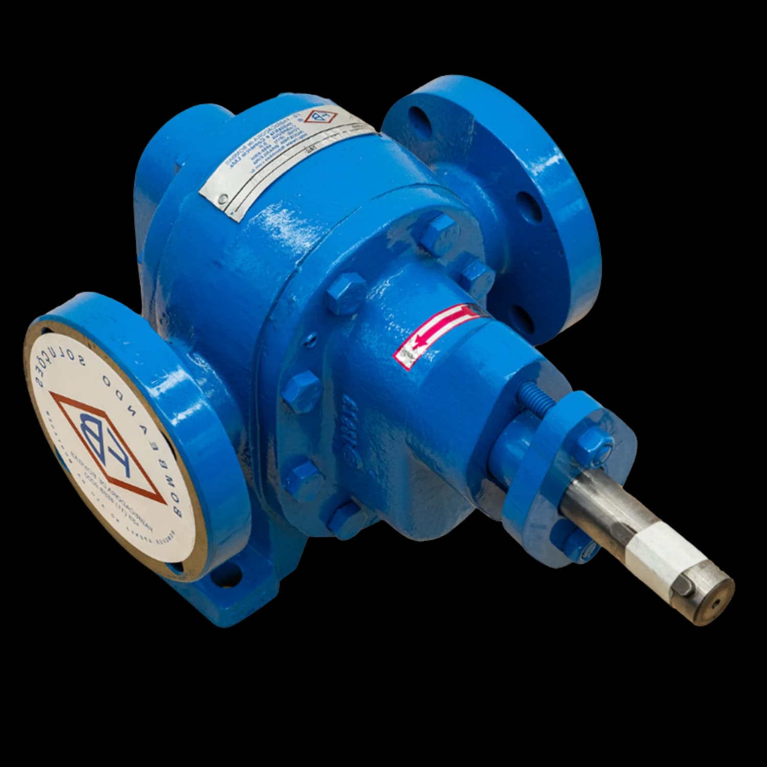
Technical specifications.
Reference photographs for this connection size. The supplied assembly depends on the selected configuration.
- Maximum catalog flow
- 100 L/min
- Maximum pressure
- 14 kgf/cm²
- Maximum speed
- 1,150 rpm
- Maximum viscosity
- 50,000 SSU
- Series maximum temperature
- 500 °C
- Weight
- 26 kg
- Inlet
- Ø 1.1/2" flange ANSI B16.5 150 lbs
- Outlet
- Ø 1.1/2" flange ANSI B16.5 150 lbs
Limits depend on the configuration and do not describe a single duty point. Check the curve and assess flow, pressure, viscosity and temperature together.
Technical source: FBE manual MTEC-01/01.Construction data · FBE 1.1/2″
Manual MTEC-01/01, Table 5- Gear diameter
- 68 mm
- Gear length
- 60 mm
- Number of teeth
- 14
- Standard shaft diameter
- 23 mm
- Gears
- 2 helical: 1 drive and 1 driven
- Mechanical seal size
- 7/8″
- Packing cross-section
- 1/4″
- Shaft diameter with external bearing
- 22.22 mm
- Hydrostatic test
- 10 kgf/cm²
- Direction of rotation
- Clockwise, with counter-clockwise option (viewed from the drive end)
CA · With heating chamber
Models at this connection size
Each code opens its own specification sheet. Compare flow rates and construction before selecting.
The drawing for this size.
Side and front views with the installation dimensions for this connection size. Tap the drawing to enlarge it and check each dimension.
Installation data
- Inlet
- Ø 1.1/2" flange ANSI B16.5 150 lbs
- Outlet
- Ø 1.1/2" flange ANSI B16.5 150 lbs
- Weight
- 26 kg
- Maximum viscosity
- 50,000 SSU
Dimensions in millimetres, per section 6 of the manual.
Your duty point, in detail.
Flow and power reference values by speed and discharge pressure. Check manual MTEC-01/01 for selection conditions.
| Pressure (kgf/cm²) | 1,150 rpm | 850 rpm | ||
|---|---|---|---|---|
| Flow (L/min) | Power (cv) | Flow (L/min) | Power (cv) | |
| 0 | 100 | 3 | 70 | 1.5 |
| 2 | 99 | 4 | 69 | 2 |
| 4 | 98 | 5 | 68 | 2.5 |
| 6 | 97 | 6 | 67 | 3 |
| 8 | 96 | 7 | 66 | 3.5 |
| 10 | 95 | 8 | 64 | 4 |
| 12 | 93 | 9 | 62 | 4.5 |
| 14 | 90 | 10 | 60 | 5 |
Blank cell: point outside the published range for that speed.
Speed by viscosity
Manual MTEC-01/01, Table 2| Viscosity (SSU) | Speed (rpm) | Drive |
|---|---|---|
| 250–2,500 | 1,150 | Direct |
| 2,500–7,500 | 850 | Direct |
| 7,500–10,000 | 700–500 | Pulley or gear reducer |
| 10,000–50,000 | 500–300 | Pulley or gear reducer |
Motor power margin
Manual MTEC-01/01, Table 4| Absorbed power | Recommended margin |
|---|---|
| Up to 2 cv | 50% |
| 3 to 5 cv | 30% |
| 6 to 10 cv | 25% |
| 11 to 25 cv | 15% |
| Above 25 cv | 10% |
Add the margin to the absorbed power at the duty point to choose a commercial motor (cv is metric horsepower).
Inside the FBE 1.1/2".
The final configuration depends on the fluid and operating conditions. Materials and options below describe available supply configurations.
Material options by component
Construction options for the FBE series. Each component material, seal and accessory is selected for the fluid and operating conditions. Confirm the available configuration for the model in the supply specification.
- Casing and covers
- ASTM A48 CL30 cast iron, ASTM A536 60-40-18 ductile iron, ASTM A216 WCB carbon steel or ASTM A743 CF8M stainless steel.
- Shafts and gears
- SAE 1045 steel or AISI 316L stainless steel. Special treatments on request.
- Bushings
- Self-lubricating bronze, cast iron, PTFE (Teflon), graphite or white metal.
- Relief valve
- Brass or AISI 304 stainless steel.
Specify the assembly for the operating conditions
Fluid and duty point
Provide the fluid, flow, differential pressure, temperature and viscosity at pumping conditions. Review these together with speed and suction conditions. Also state the supply frequency (50 or 60 Hz): a gear pump moves a volume of liquid with each shaft revolution, so the flow depends on the speed set by the motor and drive.
Sealing and materials
Confirm each component material and the seal for the configuration. Packing, mechanical seals and lip seals are series options; availability depends on the supplied configuration.
Heating
The CA chamber circulates a heating fluid.
Assess each limit for the model and configuration, without assuming simultaneous maxima. Before installation, confirm connections, flange class, sealing and the dimensional drawing.
Sealing per the manual
Manual MTEC-01/01, sections 2 and 3- Gland packing — compressed by the gland follower and adjusted by a hex nut
- Mechanical seal type 21 — ceramic × graphite × viton, AISI 304 spring
- Lip seal — installed in a specially manufactured cover or casing
- Magnetic coupling — special sealing where no leakage is allowed, with corrosive, toxic or explosive fluids
Accessories per the manual
Manual MTEC-01/01, sections 2 and 3- Drive
- Electric motor or combustion engine.
- Coupling
- Flexible, with or without spacer, FB standard or other manufacturers.
- Coupling guard
- FB standard guard in carbon steel or non-sparking material.
- Baseplate
- Welded structural steel or "U" channel plate.
- Nameplate
- Aluminium or stainless steel.
Auxiliary connections
Manual MTEC-01/01, Table 17, column 1.1/2″| Connection | Function | Thread |
|---|---|---|
| D1 | Drain | 5/16″ BSW |
| D2 | Drain | 5/16″ BSW |
| D31 | Seal gland drain | 1/4″ NPT |
| M11 | Measuring instrument | 1/4″ NPT |
| M21 | Measuring instrument | 1/4″ NPT |
| C1 | Heating chamber inlet | 3/8″ BSP |
| C2 | Heating chamber outlet | 3/8″ BSP |
| F11 | Seal flush | 1/4″ NPT |
| Q11 | Seal quench | 1/4″ NPT |
1 Provided only according to the application and the customer’s request.
C1/C2: Chamber sizes for supply without interconnecting piping.
Parts and spares.
Standard parts list from the manual for the packed construction, with part numbers per DIN EN 24250. The optional assemblies show what each configuration adds.
Parts list · Table 10 · FBE 1.1/2″–2″–3″ with packing
MTEC-01/01 · DIN EN 24250| Part no. | Description | Qty |
|---|---|---|
| 102 | Casing | 1 |
| 163.1 | Front cover | 1 |
| 163.2 | Rear cover | 1 |
| 210 | Drive shaft | 1 |
| 213 | Driven shaft | 1 |
| 400.1 | Gasket (cover / casing) | 2 |
| 452 | Gland follower | 1 |
| 461 | Packing ring | 5 |
| 540 | Bushing | 4 |
| 560 | Dowel pin | 4 |
| 87-2.1 | Drive gear | 1 |
| 87-2.2 | Driven gear | 1 |
| 901 | Hex bolt | 16 |
| 902 | Stud | 2 |
| 912 | Plug | 2 |
| 920 | Hex nut | 2 |
| 940.1 | Key | 1 |
Optional assemblies
Mechanical sealTable 12
| Part no. | Description | Qty |
|---|---|---|
| 163.3 | Rear cover for the seal | 1 |
| 210.1 | Drive shaft for mechanical seal | 1 |
| 400.3 | Gasket (gland plate / flange) | 1 |
| 433 | Mechanical seal | 1 |
| 471 | Gland plate | 1 |
| 574 | Spring retainer | 1 |
| 540.2 | Mechanical seal bushing | 1 |
| 723 | Flange | 1 |
| 914.2 | Socket head cap screw | 4 |
| 914.3 | Socket head cap screw | 1 |
| 916 | Socket set screw | 3 |
| 940.1 | Key | 1 |
Lip sealTable 13
| Part no. | Description | Qty |
|---|---|---|
| 163.4 | Rear cover for the seal | 1 |
| 210 | Shaft | 1 |
| 421 | Lip seal | 2 |
| 940.1 | Key | 1 |
Heating chamber (CA)Table 14
| Part no. | Description | Qty |
|---|---|---|
| 102.4 | Casing with heating chamber | 1 |
| 400.2 | Gasket (blind cover / casing) | 2 |
| 901.3 | Hex bolt | 8 |
| 456 | Flow reducerOnly on FBE 1.1/2″, 3″ and 4″ M6 CA (manual note) | 4 |
Parts that Table 14 adds for the chamber version. The complete list for this version, in Table 14 of the manual (p.14), differs from the standard list.
External bearingTable 15
| Part no. | Description | Qty |
|---|---|---|
| 210.2 | Drive shaft for external bearing | 1 |
| 330 | Bearing bracket | 1 |
| 321 | Rolling bearing | 1 |
| 910.1 | Key | 1 |
Relief valveTable 16
| Part no. | Description | Qty |
|---|---|---|
| 484 | Spring support | 1 |
| 580 | Cap nut | 1 |
| 59-6 | Ball | 1 |
| 71-2 | Nipple | 1 |
| 756 | Spring | 1 |
| 757 | Adjusting screw | 1 |
| 924 | Adjusting nut | 1 |
Use cover (163) for the valve.
Documentation to specify.
The pump code, speed and construction identify the correct document for your selection.
Product catalogues

These catalogues complement the technical manuals. For sizing and operating limits, consult the specific documentation and engineering team.
Documents for this size
Files cover configurations at this connection size. Check the code, variant and speed stated in each document before selecting the pump set.
Before specifying.
When selecting the FBE 1.1/2", assess the fluid and installation conditions for applications such as large flow, large scale processes, heavy industry. The reference speed range for this connection size is 300–1150 rpm; viscosity and the drive determine the appropriate speed. Use code FBE-1.1/2 to compare curves, materials and options for the same configuration.
Questions about the FBE 1.1/2".
What is the reference flow for the FBE 1.1/2"?
The published reference for this model is 100 L/min, with a maximum speed of 1,150 rpm. Check the flow at the required discharge pressure in the model table or the FBE manual. Maximum flow and maximum pressure are separate limits, not one duty point.
Can the FBE 1.1/2" have a heating chamber?
The CA heating-chamber option is available at this connection size. Define the heating medium, fluid viscosity and temperature with FB Bombas before selecting the seals, drive and duty point.
What should I provide to specify the FBE 1.1/2"?
Provide the fluid, required flow, differential pressure, operating temperature and viscosity. The published viscosity limit for this size is 50,000 SSU; speed, materials and sealing must be selected for the actual service. Include suction conditions and the intended drive.
How do I confirm availability and the dimensional drawing?
Request a quotation using code FBE-1.1/2. FB Bombas confirms the available configuration, lead time and dimensional drawing for supply. Existing dimensional files cover specific arrangements; check the variant and connections before defining the installation.
How many gears does the FBE 1.1/2" have?
Per Table 5 of manual MTEC-01/01, the FBE 1.1/2" uses two helical gears, one drive and one driven, with a 68 mm gear diameter, 60 mm gear length and 14 teeth, on a 23 mm standard shaft. The hydrostatic test is 10 kgf/cm², and rotation is clockwise with a counter-clockwise option, viewed from the drive end.
Which speed suits the FBE 1.1/2" for each viscosity?
Table 2 of the manual sets the speed by viscosity for this size: 250–2,500 SSU: 1,150 rpm (direct), 2,500–7,500 SSU: 850 rpm (direct), 7,500–10,000 SSU: 700–500 rpm (pulley or gear reducer) and 10,000–50,000 SSU: 500–300 rpm (pulley or gear reducer). Above the direct-drive range, a pulley or gear reducer lowers the speed; the duty point and the curve confirm the final choice.
Which spare parts make up the FBE 1.1/2"?
In the packed construction, Table 10 of the manual lists 17 items numbered per DIN EN 24250, starting with casing, front cover, rear cover, drive shaft, driven shaft and gasket (cover / casing). The mechanical seal, lip seal, heating chamber (CA), external bearing and relief valve options have their own parts lists. Quote code FBE-1.1/2 and the part number when requesting spares.
Your process. The right configuration.
Share the fluid, flow, pressure and operating temperature. Your selected model is included in the request to our technical team.
Confirm availability and lead time in your quotation, including special materials and configurations.
Series rating FBE: 4.8/5 · 89 customer ratings
Source and scope
Consolidated figures supplied by FB Bombas from its customer ratings spreadsheet. The score and count refer to the series; they are not independent counts for each model or configuration.
Continue your comparison.
Adjacent connection sizes help you compare the catalog. Changing the model requires a new duty-point assessment.