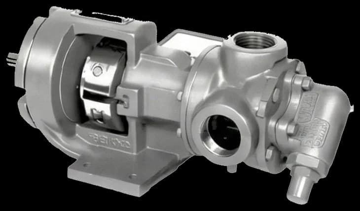
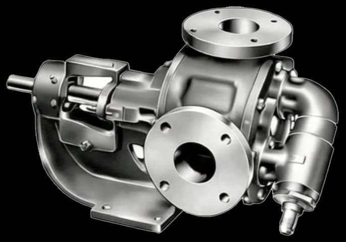
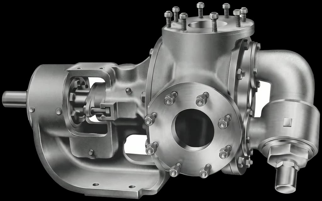
Sealing
Mechanical seal or packing, according to the configuration specified for the application.


Internal gear pump · 1½" · In-line flanges (Fig. 11).
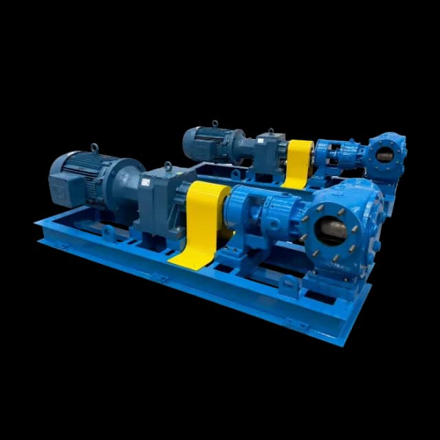
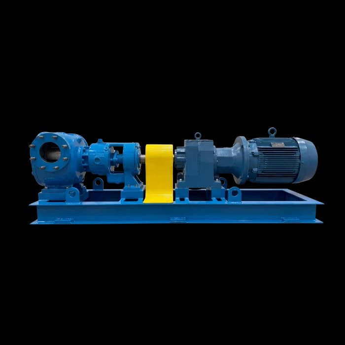
FBEI series assembly. Reference image of the line, not an individually identified image of this model.
The MAN001-10 manual figure beside this model’s dimensions. The nominal connection (A) is in inches; all other dimensions are in millimeters.
Read each letter in the stated manual drawing. Do not estimate a dimension absent from this table; check the drawing and confirm the supplied configuration.
Configuration, sealing and heating need to match the conditions of your process.
The manual identifies the rotor with shaft and the internal gear. Crescent geometry separates suction from discharge and transfers fluid by positive displacement. Check the construction and parts of the selected configuration.
Size and weight do not determine flow, pressure, speed or power. These values depend on application sizing.
Mechanical seal or packing, according to the configuration specified for the application.
Where a jacket is specified for the configuration, MAN001-10 p.4 limits its circuit to steam up to 185 °C and 10 bar or thermal fluid up to 232 °C and 10 bar. These limits concern the heating circuit, not the pumped liquid.
Check the equipment configuration. Pumps without a relief valve require external protection under the manual. The relief valve must not be used to control pressure or flow.
Series features from the 2026 FBEI catalog and MAN001-10 requirements, with the page for each source.
The catalog describes self-priming as a series feature. Before startup, the manual requires priming: fill the pump and suction line and vent the air.
2026 catalog · p.3 · MAN001-10 · p.13The catalog describes the direction of rotation as reversible. Before starting, check the direction against the arrow on the pump body or coupling guard.
2026 catalog · p.3 · MAN001-10 · p.5Pumps leave the factory pre-aligned, but transport, loading and unloading usually misalign the assembly. Realign it after installation on the final base.
MAN001-10 · p.15Whenever possible, fit a 40 to 80 mesh filter, depending on the model, with the largest possible flow area to avoid cavitation. Without a permanent filter, fit a temporary cone strainer before tests and startup.
MAN001-10 · p.4Tolerances quoted from the coupling supplier’s technical catalog: radial below 0.05 mm and angular below 0.6°. Observe the gap recommended by the coupling manufacturer.
MAN001-10 · p.15Pages 5 and 13 of the manual give different instructions for valves and fluid at startup: confirm the procedure for your unit with technical service. Never run the pump without fluid inside, and do not use steam or water to clean the pump or system.
MAN001-10 · p.5 · p.13To assess oils, resins, paints, adhesives or bitumen, share composition, viscosity at startup and operating temperatures, solids content, flow and pressures. These details support compatibility assessment and configuration selection.
Materials, sealing, drive and heating are specified for the process. This model’s dimensional table does not determine those supply options.
Review series materials and optionsPump with mechanical seal from section 2 of MAN001-10 (p.7), numbered as the drawing balloons. The manual does not state quantities.
| Item | Description |
|---|---|
| 1 | Lock ring (lock washer) |
| 2 | Lock nut (locknut or lock-washer nut) |
| 3 | Capus (bearing housing cover) |
| 4 | Lip seal |
| 5 | Outer spacer collar |
| 6 | Bearing |
| 7 | Inner spacer collar |
| 8 | Ring |
| 9 | Bearing housing (aluminum) |
| Item | Description |
|---|---|
| 10 | Mechanical seal (with gland plate) |
| 11 | Bolts |
| 12 | Grease fitting |
| 13 | Bracket (bearing bracket) |
| 14 | Bracket bushing |
| 15 | Bracket gasket |
| 16 | Plug |
| 17 | Casing |
| 18 | Rotor with shaft |
| Item | Description |
|---|---|
| 19 | Internal gear |
| 20 | Internal gear bushing |
| 21 | Head gasket |
| 22 | Pin |
| 23 | Head with pin |
| 24 | Bolts |
| 25 | Relief valve gasket |
| 26 | Relief valve |
| 27 | Bolts (relief valve) |
Items 25 to 27: relief valve, for pumps supplied with one. Confirm your equipment configuration.
| Item | Description |
|---|---|
| 1 | Lock ring (lock washer) |
| 2 | Lock nut (locknut or lock-washer nut) |
| 3 | Capus (bearing housing cover) |
| 4 | Lip seal |
| 5 | Outer spacer collar |
| 6 | Bearing |
| 7 | Inner spacer collar |
| 8 | Ring |
| 9 | Bearing housing (aluminum) |
| 10 | Packing gland |
| 11 | Washer |
| Item | Description |
|---|---|
| 12 | Bolts |
| 13 | Packing rings |
| 14 | Washer |
| 15 | Bolts |
| 16 | Grease fitting |
| 17 | Bracket (bearing bracket) |
| 18 | Bracket bushing |
| 19 | Bracket gasket |
| 20 | Plug |
| 21 | Casing |
| 22 | Rotor with shaft |
| Item | Description |
|---|---|
| 23 | Internal gear |
| 24 | Internal gear bushing |
| 25 | Head gasket |
| 26 | Pin |
| 27 | Head with pin |
| 28 | Bolts |
| 29 | Relief valve gasket |
| 30 | Relief valve |
| 31 | Bolts (relief valve) |
Items 29 to 31: relief valve, for pumps supplied with one. Confirm your equipment configuration.
The manual’s spare-parts list for two years of operation. Confirm codes, quantities and materials against the equipment identification.
| Item | Description |
|---|---|
| 01 | FBEI gear pump |
| 02 | Coupling guard |
| 03 | Coupling |
| 04 | Motor |
| 05 | Base |
Product catalogues and the MAN001-10 manual are available in Portuguese. Check the configuration before installing or specifying the equipment.
Product catalogues
These catalogues complement the technical manuals. For sizing and operating limits, consult the specific documentation and engineering team.
Installation, operation, maintenance, parts and dimensions for the FBEI series.
Model-specific information and requirements documented in the FBEI manual.
The FBEI HJ12 dimensional table lists nominal size 1½" as dimension A (Fig. 11 in MAN001-10). Check the drawing for the connections and other interfaces of the configuration to be supplied.
The dimensional table gives an approximate weight of 20 kg for FBEI HJ12 (Fig. 11). This is not the shipping weight of a complete driven assembly and base; confirm the scope and total weight in the quotation.
The catalog describes self-priming as a series characteristic. For FBEI HJ12, confirm suction and startup conditions with the technical team. This does not permit dry running or automatically eliminate suction accessories: MAN001-10 requires fluid inside the pump before startup.
The catalog describes the series as reversible. Before reversing FBEI HJ12, confirm its configuration and procedure with FB. MAN001-10 requires checking the rotation arrow and keeping the relief-valve adjustment cap toward the suction side.
The manual shows mechanical-seal and packing constructions. The current catalog also lists single, double and cartridge seals for the series. Availability and seal materials for FBEI HJ12 must be specified for the fluid, temperature and operating conditions; the series list does not guarantee every option for every model.
The jacket is a series option; confirm availability for the FBEI HJ12 configuration. Where specified, MAN001-10 p.4 gives heating-circuit limits: steam up to 185 °C and 10 bar, or thermal fluid up to 232 °C and 10 bar. These are not universal pumped-fluid limits.
Confirm the relief valve in the supply specification for FBEI HJ12. Its dimensional reference is Fig. 11; the model identifier alone does not define the protection of the installation. MAN001-10 requires external protection for pumps without a relief valve and prohibits using relief to regulate pressure or flow.
MAN001-10 p.4 specifies 40 to 80 mesh depending on the model and calls for the largest possible passage area. For FBEI HJ12, confirm mesh and sizing with engineering, considering the fluid and suction conditions. This does not mean that any filter in this range prevents cavitation.
MAN001-10 p.15 states radial alignment below 0.05 mm and angular alignment below 0.6°, alongside the coupling manufacturer’s recommendations. For the FBEI HJ12 assembly, check the supplied coupling requirements and realign after installation on the final base.
The MAN001-10 p.8 spare-parts list includes internal gear, pin, support and gear bushings, packing or mechanical seal, and bearing. For FBEI HJ12, confirm part codes, quantities and materials using the equipment identification. The two-year reference supports planning; it is not a service-life guarantee or replacement interval.
MAN001-10 documents FBEI HJ12, including its Fig. 11 dimensions. Also use the data sheet and supplied-configuration documents. If procurement requires supplier registration or qualification, request the current document and check its validity and scope; it is not certification of each pump.
Share your fluid and operating conditions. Our team uses these details to assess the model, sealing and drive for your application.
Size and weight do not determine flow, pressure, speed or power. These values depend on application sizing.
Check dimensions and configurations. A nearby nominal size does not establish hydraulic equivalence or interchangeability.