

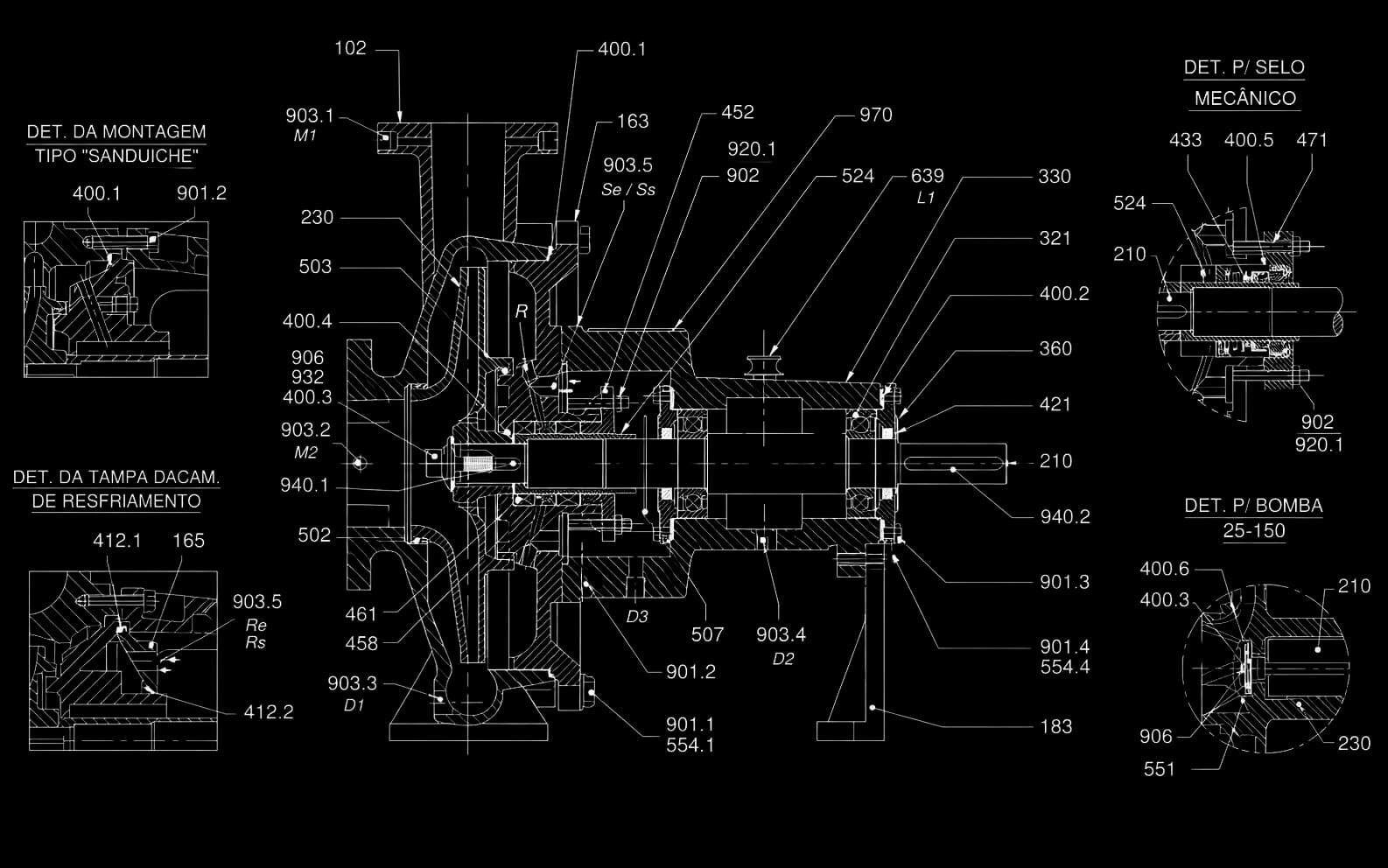
A centrifugal pump speeds up the liquid and converts that kinetic energy into pressure; the US DOE and Hydraulic Institute sourcebook sets it apart from positive displacement pumps, which squeeze the fluid directly. Centrifugal pumps are classified by five independent criteria: flow direction, number of stages, shaft orientation, casing configuration and impeller geometry. The classifications combine in the same machine. FBCN, for example, is radial, single-stage, horizontal, end-suction, back pull-out and uses a closed impeller.
At a glance
- Centrifugal pumps are classified by five criteria: flow direction, number of stages, shaft orientation, casing and impeller.
- In radial flow, the liquid enters along the shaft axis and leaves perpendicular to it; FBCN, FBOT and FBME are radial.
- The end-suction back pull-out configuration allows impeller maintenance without disconnecting the industrial process piping.
- FBCN, FBOT and FBME use closed impellers, which, according to the Hydraulic Institute, lose much less efficiency with wear than open ones.
- Higher pressures may require a multistage pump; at FB Bombas, that is the FBME Series, horizontal, with up to 300 m in the MTEC-08/01 manual.
What is the difference between radial, mixed-flow and axial pumps?
The US DOE and Hydraulic Institute sourcebook classifies pumps by the way they add energy to the fluid. Positive displacement pumps squeeze the fluid directly and include piston, screw, sliding vane and rotary lobe types, among others; centrifugal pumps, also called rotodynamic pumps, speed up the fluid, convert this kinetic energy into pressure and include axial, mixed-flow and radial types (DOE, p. 3). This article covers centrifugal pumps.
Per the Hydraulic Institute (HI) definitions, in the radial pump the liquid enters the impeller eye along the shaft axis and leaves perpendicular to it; in the mixed-flow pump, it leaves at about 45° to the shaft; in the axial pump, it enters and leaves along the axis. The higher the flow relative to the head, the larger the waterways and the smaller the diameter; the impeller shifts from radial to mixed flow and, at the far end, to axial.
The axial impeller resembles a boat propeller. FBCN, FBOT and FBME are radial. In the HI chart, the types follow one another along specific speed, calculated at the best efficiency point (BEP), with the maximum-diameter impeller, at a given speed and with the head per stage: in metric units, ns = n·Q^0.5/H^0.75, with n in rpm, Q in m³/s and H in m; in US customary units, the value is 51.6 times higher.
Part of the literature calculates specific speed with the flow per impeller eye rather than the total flow, and HI cautions users to check the calculation basis before comparing values. Compare numbers only within the same convention.
| Direction | Fluid trajectory | Dominant characteristic | FB series |
|---|---|---|---|
| Radial | Enters along the shaft axis and leaves perpendicular to it | Head at moderate flow | FBCN, FBOT and FBME |
| Mixed flow | Enters along the shaft axis and leaves at about 45° to it | Head × flow compromise | — |
| Axial | Enters and leaves along the shaft axis | High flow at low head | — |
When to use a single-stage or multi-stage pump?
The single-stage pump has one impeller and generates the full head in a single step; the multistage pump has two or more impellers in series, whose heads add up at the same flow. FBCN is single-stage: the MTEC-03/00 manual registers 54 models and head up to 135 m. The decision starts from the flow and head point and from the NPSH, not from an isolated universal limit.
According to HI, higher pressures may require a multistage pump. Compare the alternatives by required flow, head, speed, suction condition and mechanical limits, using the drawings, curves and scope of each; the number of impellers alone does not define cost or ease of maintenance.
At FB Bombas, the multistage series is FBME: horizontal, made up of a suction casing, a discharge casing and stage casings joined by external tie rods, with closed radial impellers mounted in diffusers. The MTEC-08/01 manual gives up to 400 m³/h and 300 m, general limits that do not occur together, in sizes from 3″ to 6″; the maximum number of stages falls as size and speed increase. Confirm the duty point and the model curve.
| Configuration | Number of impellers | Hydraulic effect | FB series |
|---|---|---|---|
| Single-stage | 1 | Full head generated in a single step | FBCN and FBOT |
| Multistage | 2 or more in series | Stage heads add up at the same flow | FBME |
What is the difference between horizontal and vertical centrifugal pumps?
Horizontal and vertical describe shaft orientation, but each covers several arrangements. In HI nomenclature, horizontal overhung pumps can be frame mounted, foot mounted or centerline mounted; the vertical pumps include in-line and vertically suspended designs. FBCN, FBOT and FBME are horizontal.
On the FBCN, back-pull-out construction, in the words of the manual, allows the bearing section to be removed from the volute without disconnecting or misaligning the pumping piping, which makes assembly, disassembly and maintenance easier. In the layout, use the configuration drawing to provide the axial removal space and access to the coupling.
Among vertically suspended pumps, HI lists submersible and discharge-through-column arrangements. In these cases, submergence enters the selection, the vertical distance from the free surface of the liquid to the pump inlet: it adds to the available NPSH, a minimum submergence prevents strong air-core vortices, and it may need to increase to meet the required NPSH.
The vertical in-line pump is another machine, with suction and discharge in line. So shaft orientation alone does not guarantee flooded suction, complete drainage or lower cost; compare the drawings, the minimum level, the access and the lifting provisions.
| Orientation | Arrangements (HI nomenclature) | What to plan for in the installation | Examples |
|---|---|---|---|
| Horizontal | Overhung (frame, foot or centerline mounted) or between bearings | Axial removal space and coupling access | FBCN, FBOT and FBME |
| Vertical | In-line or vertically suspended, among others | Vertical removal, minimum level and submergence | In-line in the piping; suspended in a sump or tank |
What changes between end-suction, split-case and in-line pumps?
End-suction is the pump in which the liquid reaches the impeller eye in a straight line, with no turns or bends, and the impeller is overhung. Split-case is the axially split casing, with the impeller between bearings. In-line is the pump with suction and discharge in line. FBCN is end-suction and back-pull-out and follows ASME B73.1 mechanically, which does not establish dimensional interchangeability with every pump under that standard.
On the FBCN, the volute is cast in one piece, stands on its own feet and has a wear ring on the suction side. FBOT is also end-suction and back-pull-out, with the same removal of the bearing section without disconnecting the piping, according to the MTEC-16/00 manual; the volute is cast without feet, the bearing frame comes in groups 3 and 4, and the coupling is flexible, with or without spacer.
In the split-case pump, the casing is axially split, and the suction and discharge nozzles are typically cast integral with the lower half: the upper half is unbolted, and the rotating assembly comes out whole, with shaft, impeller, sleeves and bearing housings. In this arrangement, the typical impeller has two eyes, each receiving half of the flow, and HI points to the two-inlet impeller for high flows.
In fire protection, according to HI, NFPA 20 permits volute-type centrifugal pumps of end-suction, vertical in-line and split-case design. In HI nomenclature, circulators are also in-line, and horizontal. For any casing, check the nozzles, the removal direction and the coupling access on the configuration drawing.
| Casing | Nozzle geometry | Maintenance access | Typical application |
|---|---|---|---|
| End-suction | Axial suction, radial discharge | Back-pull-out without disconnecting the piping (FBCN and FBOT) | Chemical and industrial process; fire protection |
| Split-case | Casing split at the shaft plane | Upper half comes off; nozzles stay on the lower half | High flow (two-inlet impeller); fire protection |
| In-line | Suction and discharge in line | Check on the configuration drawing | Circulation; fire protection (vertical in-line) |
Which impeller to choose: closed, semi-open or open?
HI describes three configurations: the open impeller has neither a front nor a rear shroud, the semi-open has only the rear one, and the enclosed has both. FBCN, FBOT and FBME use closed impellers: the FBOT and FBME manuals state it in the text, and the FBCN manual shows it in the sectional drawing. For solids, check the allowable passage, size, concentration and abrasiveness; the impeller name alone does not settle the selection.
According to HI, the enclosed impeller costs more to make, is harder to clean and handles fewer fluid types than the open impeller, but it is stronger and loses much less efficiency over the pump’s life. Internal leakage is controlled by running clearances. On the FBCN, the manual provides a wear ring on the casing, on the suction side, and on the impeller, on the pressure side, except in sizes 25-150, 32-125 and 32-125.1.
In open and semi-open impellers, the gap between the vanes and the casing grows with wear and lets liquid leak back to suction, so efficiency drops; for the same reason, HI notes that the enclosed impeller does not need such a precise axial setting. Open impellers are typical of smaller pumps, axial-flow pumps and solids-handling pumps, and the semi-open design shares some of the advantages and drawbacks of each.
The FBCN and FBME manuals indicate the series for clean or turbid liquids and ask for FB to be consulted for fluids with suspended solids; the FBOT manual rules out abrasive particles. Compare the free passage and the curve of each alternative, without assuming that every open impeller handles fibres.
| Impeller | Construction | Where it is used | Operational trade-off |
|---|---|---|---|
| Closed | Front and rear shrouds | Clean or turbid liquids (FBCN and FBME) and thermal oil (FBOT) | Costs more; loses much less efficiency with wear |
| Semi-open | Rear shroud only | Middle ground between open and enclosed | Loses efficiency as the clearance grows; confirm passage and clearances |
| Open | No front or rear shroud | Smaller pumps, axial-flow and solids-handling pumps | Cheaper and easier to clean; loses efficiency with wear |
How are the FBCN, FBOT and FBME series classified?
FBCN is radial, single-stage, horizontal, end-suction, back-pull-out and closed-impeller; the MTEC-03/00 manual registers 54 models, DN 25 to DN 300, up to 2,200 m³/h and 135 m. FBOT has the same classification and pumps organic thermal oils up to 350 °C. FBME is radial, multistage and horizontal, with closed impellers in diffusers, up to 400 m³/h and 300 m. These are general limits from the manuals, not simultaneous and not a model selection.
Sealing sets the series apart: FBOT has double sealing, with graphite packing in the region in contact with the thermal oil and a mechanical seal inside the bearing frame, immersed in the bearing-frame oil; FBCN and FBME accept packing or a mechanical seal. FB has a test bench per ANSI/HI 14.6, but which tests, balancing and reports accompany each pump is defined in the proposal.
Buyers looking for a horizontal centrifugal pump with a mechanical seal will find two FB series. On the FBCN, Table 3 of the MTEC-03/00 manual (p. 7), which gives pressure limits by maximum temperature, sets 10 bar at 90 °C for the mechanical-seal execution. With packing, the limits are 12 bar from −28 to 65 °C, 11 bar at 93 °C and 10 bar at 105 °C with 125 lbs flanges, and 16 bar with 250 lbs flanges.
On the FBME, Figure 3 of the MTEC-08/01 manual (p. 10) calls code S the single-acting mechanical seal, balanced or unbalanced, for temperatures up to about 105 °C, depending on the seal manufacturer and without cooling; suction pressure enters the seal selection. FBOT, as described above, uses double sealing, and the mechanical seal article compares seal types and packing.
To choose between FBCN, FBOT and FBME, send the liquid, temperature, flow, head, suction condition, suspended solids and the intended sealing. With these data, FB Bombas application engineering indicates the series, the model and the curve for the duty point.
| Criterion | FBCN Series | FBOT Series | FBME Series |
|---|---|---|---|
| Flow direction | Radial | Radial | Radial |
| Number of stages | Single-stage | Single-stage | Multistage |
| Shaft orientation | Horizontal | Horizontal | Horizontal |
| Casing | End-suction, back-pull-out | End-suction, back-pull-out | Stage casings with tie rods; horizontal suction and vertical discharge |
| Impeller | Closed, radial single-suction | Closed, radial single-suction | Closed, radial single-suction, in diffusers |
| Typical application | Clean or turbid liquids — up to 2,200 m³/h and 135 m | Organic thermal oils up to 350 °C | Clean or turbid liquids — up to 400 m³/h and 300 m |