

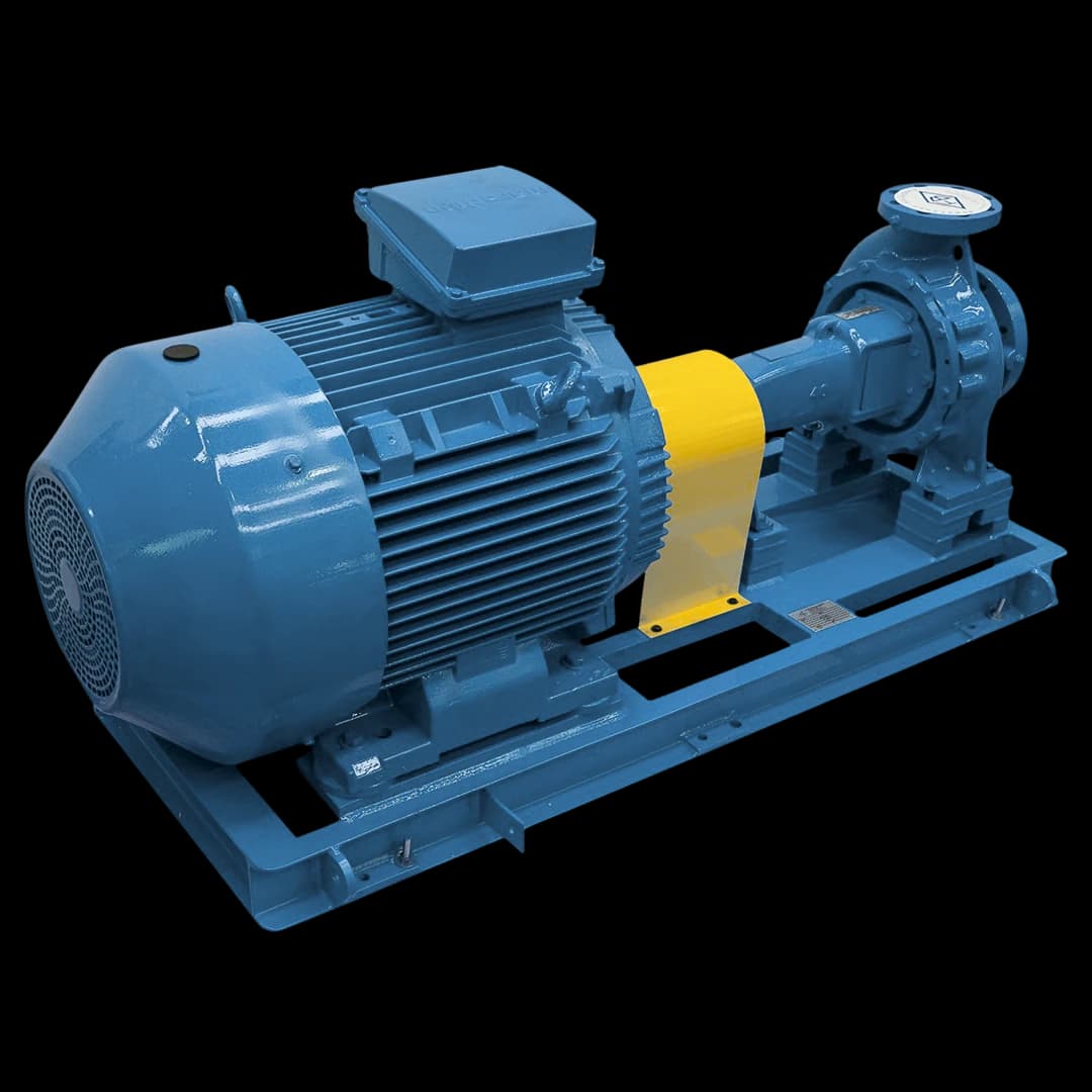
A motor-pump assembly is a pump supplied with its driver on a common baseplate. In the FB manuals, the assembly accessories are the driver (electric motor or, depending on the series, a combustion engine), the flexible coupling with or without spacer, the coupling guard and the steel baseplate. The FBME and FBEI manuals state that the pump leaves the factory pre-aligned but that transport usually misaligns the set; alignment is redone at final installation. Confirm components and tests in the FB Bombas proposal.
At a glance
- A motor-pump assembly is the pump with motor, coupling, coupling guard and baseplate: the five items of the assembly parts list in the FBEI manual (MAN001-10, p.8).
- The motor carries a margin over the pump’s required power: in the FBCN and FBOT manuals, about 20% up to 2 cv and 10% above 20 cv; in the FBE manual, from 50% up to 2 cv to 10% above 25 cv.
- In the FBME and FBEI manuals, the set leaves pre-aligned, but transport usually misaligns it; both call for realignment at final installation, within the coupling supplier’s tolerance (radial below 0.05 mm and angular below 0.6°).
- The coupling guard is carbon steel or non-sparking material; in confined spaces, the FBEI and FBME manuals require brass or aluminium and a stainless-steel nameplate.
- Factory assembly does not change suction: NPSH and margin are assessed for the actual pump, installation and operating range.
1. What is a motor-pump assembly
A motor-pump assembly, also called a pump set or pump unit, is a pump supplied with its driver on a common baseplate, connected to it by a coupling and with a guard over the rotating parts. This guide focuses on the industrial configuration with pump and motor mounted on the baseplate according to the assembly drawing. Other constructions exist; confirm the drawing and the limits of the offered configuration.
In the FB technical manuals these items appear as pump accessories: FBCN (MTEC-03/00, item 5), FBE (MTEC-01/01, item 3) and FBOT (item 4) list the driver, coupling, coupling guard and baseplate; the FBE manual adds the nameplate, in aluminium or stainless steel. The dimensions on the assembly drawing are what the baseplate seat in the foundation is prepared from (MSERV-08/01, 5.1).
Transport, fastening of the baseplate and piping loads can change the alignment. For that reason, a field check remains necessary even when the set was adjusted at the factory. Follow the pump and coupling manuals and record the results.
2. Motor-pump assembly components
The assembly parts list in the FBEI manual (MAN001-10, p.8) has five items: pump, coupling guard, coupling, motor and baseplate. What changes from one series to another is in the manuals:
- Pump: series and configuration selected for liquid, flow, pressure and temperature, such as FBCN, FBME, FBE, FBEI or FBOT. The series sets the speed range and, with it, whether the set needs a gear reducer or pulley.
- Driver: electric motor on every series; the FBCN manual also lists a diesel engine, and the FBE manual a combustion engine. Power, speed, voltage, frequency, duty and environment apply to the full operating range.
- Transmission: flexible coupling with or without spacer, FB standard or from other makers. On the FBE with very viscous liquids, Table 2 of MTEC-01/01 lowers speed from 1,750 down to 150 rpm, with a pulley or gear reducer.
- Coupling guard: FB standard guard in carbon steel or non-sparking material. The FBME manual (MSERV-08/01, 5.7) treats it as mandatory under Brazil’s NR-12 and requires it fixed to the baseplate, clear of the coupling.
- Baseplate: welded structural steel on the FBCN and FBE, U-channel plate on the FBE and FBOT. The FBCN has a 1″ NPT baseplate drain (MTEC-03/00, Table 6). The FBCN’s mechanical ASME B73.1 reference does not prove standardised dimensions for every baseplate.
3. Factory assembly advantages
Mounting pump, coupling and motor on the baseplate at the factory puts integration under one supplier; in the FBME and FBEI manuals, the set leaves pre-aligned. The gain has a limit: the FBME (MSERV-08/01, 5.4) and FBEI (MAN001-10, item 8) manuals warn that transport, loading and unloading usually misalign the set, and that alignment is redone after final installation. What factory assembly offers:
- Integration and initial adjustment of included components
- Factory tests and records where included in scope
- Identified interfaces for planning site installation
- Responsibilities and warranty terms documented in the proposal
- Compatibility checks for selected components
To lift the set, the FBEI manual (MAN001-10, p.11) says a single lifting eye must not be used, neither the motor’s nor the pump’s. On site, follow the manual sequence for foundation, connections, alignment, checks and startup.
4. How to specify a motor-pump assembly
To request a motor-pump assembly from FB Bombas, provide the data below. With them, application engineering selects the pump, calculates the required power at the duty point and chooses the commercial motor with the margin the series manual recommends.
The margin changes from one series to another: up to 2 cv, it is about 20% on the FBCN and FBOT and 50% on the FBE. The table reproduces each manual’s ranges; cv is the metric horsepower used in the manuals.
- Fluid data — name, viscosity, density, operating temperature and solids presence
- Operating conditions — flow (m³/h or L/min), pressure (bar or kgf/cm²), available NPSH
- Available electrical voltage — 220V, 380V, 440V, frequency (50 or 60 Hz)
- Driver — electric motor or combustion engine, speed and, if the pump turns slower than the motor, gear reducer or pulley
- Environment — area classification and, in confined spaces, a non-sparking coupling guard (brass or aluminium) and a stainless-steel nameplate, as the FBEI and FBME manuals require
- Materials — cast iron, stainless steel or special alloys per chemical compatibility
- Scope — coupling with or without spacer, baseplate type, tests and documents supplied, such as the assembly drawing and data sheet
| Manual | Pump required power | Motor margin |
|---|---|---|
| FBCN (MTEC-03/00, Table 2) and FBOT (Table 2) | up to 2 cv | about 20% (minimum 1.5 cv) |
| FBCN and FBOT | up to 20 cv | about 15% |
| FBCN and FBOT | above 20 cv | about 10% |
| FBE (MTEC-01/01, Table 4) | up to 2 cv | 50% |
| FBE | 3 to 5 cv | 30% |
| FBE | 6 to 10 cv | 25% |
| FBE | 11 to 25 cv | 15% |
| FBE | above 25 cv | 10% |
5. Alignment and tolerances
The FBME (MSERV-08/01, 5.4) and FBEI (MAN001-10, item 8) manuals quote, from the coupling supplier’s catalogue, a radial tolerance below 0.05 mm and an angular tolerance below 0.6°. The installed coupling’s limit governs. A flexible coupling absorbs small deviations in service, but that does not justify poor alignment: a misaligned machine causes vibration, premature wear and higher energy use.
The field sequence in MSERV-08/01 (5.1 to 5.5) is: level the baseplate with shims, without tightening the anchor bolts; align the flanges with the piping; tighten the anchor bolts and recheck alignment; grout; connect the piping only after curing; and, with the piping bolts tightened, correct coupling alignment if needed.
The pump must not support the piping: the FBME manual names cracked casings and a misaligned set as the consequence and calls for expansion joints when the liquid temperature varies. Recheck frequency depends on the maintenance plan and interventions; there is no universal interval.
6. NPSH and cavitation in the motor-pump assembly
Check installation NPSHa and configuration NPSHr across the intended range, with a service-appropriate margin. A 1 m reference does not universally approve a pump set. Provide level, pressure, temperature, flow and suction losses for selection.
Factory assembly does not change the supply conditions on site. Noise, vibration or loss of performance require a diagnosis of both the pump and the system; the time to a failure cannot be estimated merely from suspected cavitation.
To monitor suction, the FBME manual recommends a compound gauge on the suction line and a pressure gauge on the discharge, scaled to about 150% of the highest pressure, with an isolation valve opened only for readings (MSERV-08/01, 5.8).
7. Vibration and predictive maintenance
Vibration assessment must identify the pump type, power, support, measurement points, direction and measured quantity. ISO 10816-7 covers rotodynamic pumps within its scope, not every gear pump set. Define limits and a baseline compatible with the configuration and compare measurements taken under the same conditions.
Plan monitoring according to criticality and operating conditions. Confirm the sensor mounting points and their compatibility with the equipment. Frequency, investment and return require plant data; there is no cost percentage or guaranteed return that applies to every set.
In operation, the FBME (MSERV-08/01, 6.2) and FBEI (p.13) manuals accept a bearing-housing temperature up to 50 °C above ambient, without exceeding 90 °C in total, and call for checks of abnormal vibration and noise. In the MSERV-08/01 preventive maintenance, vibration levels are part of the monthly inspection (7.1.2).