

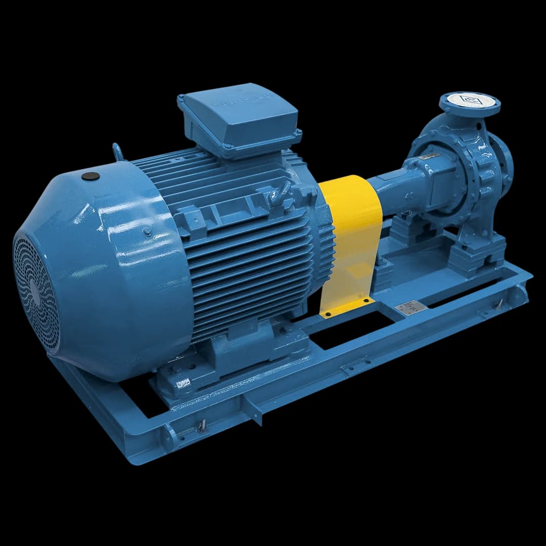
ISO 10816-7 evaluates the vibration of industrial rotodynamic pumps above 1 kW by RMS velocity, in mm/s, measured on the bearing housings. There are four zones: A (newly commissioned pump), B (unrestricted continuous operation), C (limited operation) and D (vibration severe enough to damage the machine). The limits depend on the category (I, high reliability; II, general use) and on power. According to the Europump summary, for category II up to 200 kW, zone A goes up to 3.2 mm/s, B up to 5.1 and C up to 8.5; for category I up to 200 kW, up to 2.5, 4.0 and 6.6 mm/s.
At a glance
- ISO 10816-7 evaluates industrial rotodynamic pumps above 1 kW by RMS velocity in mm/s on the bearing housings; it remains published, and ISO has registered the ISO 20816-7 project to replace it.
- According to the Europump summary, for category II up to 200 kW, zone A goes up to 3.2 mm/s, B up to 5.1 and C up to 8.5; for category I up to 200 kW, up to 2.5, 4.0 and 6.6 mm/s.
- Measure on each bearing in the vertical, horizontal and axial directions, always at the same point and in normal operation, and compare the trend with the reference recorded after commissioning.
- Imbalance appears at 1× running speed radially; angular misalignment at 1× axially and parallel misalignment at 2× radially; a bearing defect at non-integer multiples of running speed.
- Balancing is a separate check: ISO 21940-11 sets the residual unbalance tolerance of the rotor, and the FBME service manual specifies grade G6.3.
1. ISO 10816-7 — standard specific to rotodynamic pumps
The ISO 10816 series evaluates machine vibration by measurements on non-rotating parts. Part 7 covers rotodynamic pumps for industrial applications with nominal power above 1 kW, with measurements on the bearing housings and also on the shafts. According to the Europump guide, the zone limits apply to impellers with more than 3 vanes, and pumps designed for solids or waste water vibrate more.
In the FB line, the FBCN and FBOT centrifugal pumps and the FBME multistage centrifugal pump are within scope. The FBE and FBEI are gear pumps, positive displacement, and fall outside it; for them, alignment and vibration follow each series manual. ISO 10816-7 remains published, and ISO has registered the ISO 20816-7 project to replace it (ISO open data, 23/09/2026).
Parts 1 and 3 have already given way to ISO 20816-1 and ISO 20816-3. The scope of ISO 20816-3 excludes rotodynamic pumps, with a cross-reference to ISO 10816-7, and covers electric motors of any type with a flexible coupling. The limits are given as velocity in mm/s RMS; on a sine wave, RMS is 0.707 of peak, and only readings with the same frequency range and scale factor can be compared (SKF guide).
2. Severity zones A, B, C and D
According to the Europump summary, the standard sets two categories. Category I covers pumps that require high reliability, availability or safety, such as those for toxic or hazardous liquids, critical service, oil and gas, special chemical, nuclear or power plant duty. Category II covers general or less critical applications, such as non-hazardous liquids; vertical suspended pumps above 600 rpm usually fall into it. Each category has limits up to 200 kW and above 200 kW.
The zones describe the machine condition: A, vibration of a newly commissioned pump, in the preferred operating range (POR); B, unrestricted long-term continuous operation, in the allowable operating range (AOR); C, limited operation, unsatisfactory for continuous service; D, vibration severe enough to damage the machine. The table follows the Europump summary, which warns that it does not replace the text of the standard when compliance is required.
| Zone | Cat. I ≤ 200 kW | Cat. I > 200 kW | Cat. II ≤ 200 kW | Cat. II > 200 kW | Meaning |
|---|---|---|---|---|---|
| A | ≤ 2.5 | ≤ 3.5 | ≤ 3.2 | ≤ 4.2 | Newly commissioned pump, in the POR |
| B | ≤ 4.0 | ≤ 5.0 | ≤ 5.1 | ≤ 6.1 | Unrestricted continuous operation, in the AOR |
| C | ≤ 6.6 | ≤ 7.6 | ≤ 8.5 | ≤ 9.5 | Limited operation |
| D | > 6.6 | > 7.6 | > 8.5 | > 9.5 | Vibration severe enough to damage the machine |
3. Standardized measurement points — DE, NDE and axial
Measure on each pump bearing housing in the three directions: vertical, horizontal and axial. The SKF guide names the drive-end points DEV, DEH and DEA and the opposite-end points NDV, NDH and NDA. Place the sensor as close to the bearing as possible, away from painted surfaces, unloaded zones and housing splits, and avoid the casing, which may vibrate from resonance or looseness.
To compare readings, repeat the same point, marked with ink or a small conical hole, with the sensor at 90° ± 10° to the surface and steady pressure; a magnetic base or a fixed sensor is even better. Measure in normal operation, with the bearings at stable temperature and the pump at its operating point. If background vibration, with the pump stopped, exceeds 25% of the running value, corrective action may be needed to reduce its effect (Europump).
The direction already gives a clue. Horizontal readings usually show the most vibration, because the machine is more flexible in that plane, and excessive horizontal vibration is a good indicator of imbalance. Vertical readings are usually lower, because of mounting stiffness and gravity. Axial vibration should be small, but misalignment and a bent shaft increase it. Confirmation comes from the spectrum (FFT) and phase, as in the next section.
4. Seven causes of high vibration and what each one shows
In the FBME service manual (MSERV-08/01, Table 7), “excessive vibration or noise” has 23 possible causes, from suction, installation and mechanical defects. The SKF guide proposes analysis by elimination: identify in the spectrum the multiples of running speed (1×, 2×, 3×), the bearing and pump impeller frequencies, neighboring machines and, on the motor, line frequency. The causes below can coexist.
- Imbalance: vibration at 1× running speed, with the same amplitude in all radial directions and no harmonics unless severe (SKF guide). In pumps, uneven impeller wear shows up as imbalance, and cavitation erosion can unbalance the impeller (DOE/HI sourcebook). A bent shaft also gives 1×, with axial vibration. The FBME manual calls for correcting part runout and checks shaft runout at the impeller with a dial indicator, with a 0.05 mm limit.
- Misalignment: angular misalignment gives axial vibration at 1× and parallel misalignment, radial vibration at 2×, with a 180° phase shift across the coupling; with 2× between 50% and 150% of 1×, coupling damage is likely, and above 150% misalignment is severe (SKF guide). The FBME and FBEI manuals call for radial deviation below 0.05 mm and angular below 0.6°, from coupling catalogs, and realignment at final installation, because transport misaligns the set.
- Cavitation and suction: in the FBME manual, pump or suction line not completely full, excessive suction lift, insufficient NPSH, undersized or clogged foot valve and insufficient submergence. The DOE/HI sourcebook describes crackling like marbles passing through the pump; cavitation usually occurs at high flow, to the right of the curve, but it can also appear at low flow, and the vibration it induces stresses foundations and piping.
- Low flow and recirculation: the FBME manual calls for operating above minimum flow. According to the DOE/HI sourcebook, low flow creates internal recirculation at the impeller suction or discharge, with damage similar to cavitation; near shutoff, shaft deflection, vibration and bearing load increase, and bearing load is lowest at the BEP. The manufacturer indicates the POR and AOR; according to Europump, the POR is generally 70% to 120% of the BEP.
- Bearings and lubrication: the FBME manual lists wear, off-center shaft, too much or too little grease or oil, wrong installation or unsuitable type, dirt, rust from water in the bearing bracket and condensation from excessive cooling. According to the SKF guide, defects appear at non-integer multiples of running speed: BPFO (outer race), BPFI (inner race), ball frequency and FTF (cage); early on, ISO severity charts help little, and acceleration enveloping detects the defect sooner.
- Base, looseness and resonance: the FBME manual links a non-rigid foundation to vibration and calls for grouting the baseplate for solid support. According to the SKF guide, structural looseness gives 1× with a 180° phase shift between feet, baseplate and foundation when the machine rocks; component looseness gives a string of running-speed or half-speed harmonics; resonance appears as a sharp amplitude increase, with a phase change, at a forcing frequency.
- Piping: forces transmitted by piping and supports are among the misalignment causes in the SKF guide. The FBME manual aligns the suction and discharge flanges with the piping on the leveled baseplate, before tightening the anchor bolts, and checks alignment again after grouting and connecting the piping. According to the DOE/HI sourcebook, high vibration creates fatigue loads that crack supports and foundations, and a substantially oversized pump can induce it.
5. Factory and field baseline — FAT, site acceptance and balancing
ISO 10816-7 also gives acceptance values, different for the factory acceptance test (FAT) and for measurement on site, within the POR and the AOR (table, per the Europump summary). At FB, the FAT plan and the bench test report are deliverables defined per project; when vibration is part of the FAT, the standard, category, operating range, points and unit go into the test plan.
Also record a field reference after commissioning, with the operating conditions. The DOE/HI sourcebook compares measurements with data taken when the machine was first operated, and the SKF guide accepts as a baseline a reading after an overhaul or with the machine known to be running well. If the pump moves up a zone, look for what changed in the installation or the equipment: piping, alignment, suction or bearings.
Balancing is a separate check. ISO 21940-11, which replaced ISO 1940-1, sets procedures and residual unbalance tolerances for rotors with rigid behaviour: the permissible residual unbalance, the correction planes and how to account for errors in the balancing process. It is not the vibration limit of the installed pump, which is evaluated under ISO 10816-7.
According to the Europump summary, ISO 5199 and ISO 9905 call for reaching the vibration limits with balancing to grade G6.3. The FBME service manual specifies static and dynamic rotor balancing to G6.3 (item 12.2). For the other series, the grade comes from the supply documents.
| Test | Cat. I ≤ 200 kW | Cat. I > 200 kW | Cat. II ≤ 200 kW | Cat. II > 200 kW |
|---|---|---|---|---|
| FAT, in the POR | 3.3 | 4.3 | 4.2 | 5.2 |
| FAT, in the AOR | 4.0 | 5.0 | 5.1 | 6.1 |
| On site, in the POR | 2.5 | 3.5 | 3.2 | 4.2 |
| On site, in the AOR | 3.4 | 4.4 | 4.2 | 5.2 |
6. Routine monitoring program
The FBME service manual includes vibration in preventive maintenance: in the daily inspection, abnormal noise and vibration; in the monthly one, vibration levels and bearing temperature; in the six-monthly one, set alignment and retightening of pump, motor and baseplate. For other pumps, the frequency comes from criticality and history. The DOE/HI sourcebook stresses that change over time says more than a single snapshot of the spectrum.
For continuous monitoring, the Europump summary gives recommended alarm values, about 1.25 times the upper limit of zone B, and trip values, about 1.25 times that of zone C (table). Vibration should stay above the value for about 10 s before release, to avoid false alarms and trips. According to the SKF guide, if the bearing acoustic emission (SEE) rises, shorten the intervals and also track enveloping, temperature and vibration.
When consulting FB, send the pump identification, the operating point (flow, pressure and speed), the measurement points, directions, unit and frequency range, the trend and the spectra. The published after-sales services include start-up and commissioning, bench performance testing with a scope defined for the project and maintenance contracts for FB lines; the service format, checks and records are defined in the proposal.
| Limit | Cat. I ≤ 200 kW | Cat. I > 200 kW | Cat. II ≤ 200 kW | Cat. II > 200 kW |
|---|---|---|---|---|
| Alarm | 5.0 | 6.3 | 6.4 | 7.6 |
| Trip | 8.3 | 9.5 | 10.6 | 11.9 |