

Standardized centrifugal pump FBCN 150-500
Standardized centrifugal pump FBCN 150-500. Suction DN200, discharge DN150. Large capacity.
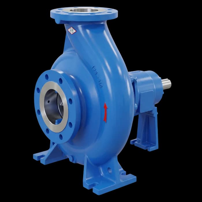
Explore the FBCN 150-500
Curve CC-0202.09, published impeller diameters and the operating envelope help prepare an engineering inquiry. For this size, request the dimensional sheet before specifying the installation.
The overall series limits do not define this model’s operating point. Confirm flow, head, impeller, material and sealing with engineering.
Series rating FBCN: 4.8/5 · 45 customer ratings
Source and scope
Consolidated figures supplied by FB Bombas from its customer ratings spreadsheet. The score and count refer to the series; they are not independent counts for each model or configuration.
How to read the designation
Designation, manual MTEC-03/00 (p. 1)- FBBrand
- CNModel: standardized centrifugal
- 150Discharge flange nominal diameter (mm)
- 500Nominal impeller diameter (mm)
Designed for clean or turbid liquids. Applications listed in the manual (p. 1):
- Chemical industry
- Petrochemical industry
- Pulp and paper industry
- Steelmaking industry
- Mining
- Food industry
- Textile industry
- Pharmaceutical industry
- Sanitation
Manual data for this size · FBCN 150-500
MTEC-03/00- Suction
- DN 200
- Discharge
- DN 150
- Bearing frame
- 70
- Maximum speed
- 1,750 rpm
- GD² of the rotating assembly with water
- 3.0000 kgm²
- Minimum / maximum flow
- 0.15 Qot / 1.1 Qot
- Axial thrust relief
- Balance holes
- Max. allowable P/n · SAE 1045 shaft
- 0.158 metric hp/rpm
- Maximum suction pressure
- 10 bar
- Cast iron flanges
- ANSI B16.1 · 125 lb FF
- Packing
- 1/2"
- Approximate weight · cast iron
- 428 kg
- Approximate weight · steel
- 440 kg
Table 1 of manual MTEC-03/00 (p. 5).
Published envelope at 1750 rpm
Ranges read from the sheet CC-0202.09- Flow up to
- 648 m³/h
- Head range
- 50–130 m
- Absorbed power
- 58–325 hp
- NPSH required
- 2–12 m
- Maximum efficiency
- 74%
- Curve code
- CC-0202.09
Ranges read from the official curve catalog; maxima do not necessarily occur at the same point. Final selection depends on impeller diameter and process conditions.
Dimensions and installation
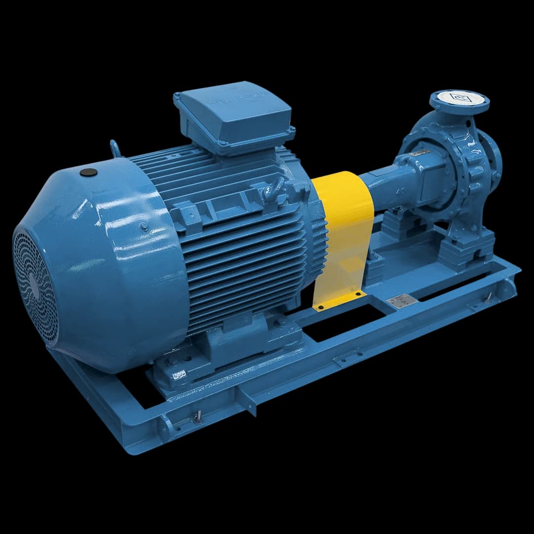
Dimensions on request
The manual directs sizes from 150-500 onward to FB for consultation. Request a dimensional sheet and the curve for your operating point before specifying the baseplate, motor or piping.
Impellers with published points
CC-0202.09 · 1750 rpm| Impeller | Tabulated flow (m³/h) | Tabulated head (m) |
|---|---|---|
| Ø 504 mm | 0–648 | 84.1–130.3 |
| Ø 480 mm | 0–604 | 69.8–118.6 |
| Ø 460 mm | 0–561 | 62.7–108.7 |
| Ø 440 mm | 0–519 | 58.5–99.1 |
| Ø 420 mm | 0–475 | 55.0–89.9 |
| Ø 400 mm | 0–432 | 50.1–80.2 |
Impellers and points extracted from the official curve sheet, at the sheet speed.
Performance curves
6 impellers with points · Ø 400–504 mm · CC-0202.09
FBCN 150-500 · CC-0202.09. Reference plot extracted from the FB Bombas technical catalog. Q × H points below apply at the stated speed. Confirm the operating point and impeller with engineering.
- Flow range
- 0–648 m³/h
- Head range
- 50.1–130.3 m
- Impeller diameters
- 504 mm · 480 mm · 460 mm · 440 mm · 420 mm · 400 mm
- Speed
- 1750 rpm
- Impeller diameter in the sheet header
- Ø 400–504 mm
- Ø 504 mm
- Ø 480 mm
- Ø 460 mm
- Ø 440 mm
- Ø 420 mm
- Ø 400 mm
Q × H points by impeller
| Flow Q (m³/h) | Head H (m) |
|---|---|
| 0 | 130.3 |
| 160 | 129.4 |
| 270 | 127.6 |
| 360 | 123.6 |
| 440 | 117.3 |
| 510 | 109.3 |
| 580 | 98.1 |
| 648 | 84.1 |
| Flow Q (m³/h) | Head H (m) |
|---|---|
| 0 | 118.3 |
| 130 | 118.6 |
| 240 | 116.7 |
| 320 | 112.8 |
| 400 | 105.8 |
| 470 | 96.7 |
| 540 | 84.3 |
| 604 | 69.8 |
| Flow Q (m³/h) | Head H (m) |
|---|---|
| 0 | 108.6 |
| 100 | 108.7 |
| 210 | 107.8 |
| 290 | 104.9 |
| 350 | 100.2 |
| 410 | 92.8 |
| 470 | 82.1 |
| 561 | 62.7 |
| Flow Q (m³/h) | Head H (m) |
|---|---|
| 0 | 98.7 |
| 110 | 99.1 |
| 200 | 98.8 |
| 270 | 96.0 |
| 330 | 91.1 |
| 390 | 83.5 |
| 460 | 71.2 |
| 519 | 58.5 |
| Flow Q (m³/h) | Head H (m) |
|---|---|
| 0 | 88.5 |
| 110 | 89.9 |
| 190 | 89.3 |
| 260 | 86.6 |
| 320 | 81.7 |
| 370 | 75.6 |
| 420 | 67.0 |
| 475 | 55.0 |
| Flow Q (m³/h) | Head H (m) |
|---|---|
| 0 | 78.6 |
| 100 | 80.0 |
| 170 | 80.2 |
| 240 | 78.1 |
| 290 | 74.6 |
| 340 | 68.6 |
| 390 | 59.9 |
| 432 | 50.1 |
Q × H points read from the official sheet for every impeller plotted, from shutoff (Q = 0) to the end of each trace.
Shaft power, NPSHr and efficiency at the operating point must be confirmed in the engineering data sheet. The reference curve does not replace technical selection.
Open sheet CC-0202.09 in the curve catalog (PDF, p. 44)Operating limits
Limits from manual MTEC-03/00 for this size and for the series. Confirm the operating point, material and sealing with engineering.
For this size · FBCN 150-500
Table 1 (p. 5)- Maximum speed
- 1,750 rpm
- Maximum suction pressure
- 10 bar
- Maximum discharge pressure
- By temperature and material: Figures 1 to 4
- Temperature without cooling chamber (Table 1)
- Packing from −50 to 105 °C; mechanical seal as recommended by the manufacturer
- Temperature with cooling chamber (Table 1)
- Table 1 gives no value for this size
- Minimum / maximum flow
- 0.15 Qot / 1.1 Qot
- Flanges for this size · cast iron
- ANSI B16.1 · 125 lb FF
- Flanges for this size · carbon steel, stainless steel, ductile iron
- ANSI B16.5 / B16.42 · 150 lb RF
Series operating data
p. 1- Sizes
- DN 25 to 300 mm
- Flow
- up to 2,200 m³/h
- Total head
- up to 135 m
- Temperatures
- up to 260 °C
- Speeds
- up to 3,500 rpm
Maximum discharge pressure curves (Figures 1 and 2): From −30 to 160 °C for the cast iron casing and from −50 to 260 °C for the carbon steel and stainless steel casing.
Pressure × temperature by sealing
Table 3 (p. 7)| Shaft sealing | Temperature | ANSI B16.1 flanges · 125 lb | ANSI B16.1 flanges · 250 lb |
|---|---|---|---|
| Packing | −28 to 65 °C | 12 bar | 16 bar |
| 93 °C | 11 bar | 16 bar | |
| 105 °C | 10 bar | 16 bar | |
| Mechanical seal | 90 °C | 10 bar | 10 bar |
Cooling and sealing liquid
Table 1 (p. 5)Table 1 gives no cooling flow for this size.
- Sealing liquid · sealing
- approx. 1 l/min
- Sealing liquid · flushing
- approx. 3 to 5 l/min
Maximum pressure by material and flange
Figures 1 to 4 (p. 6)| Material or flange | Temperature | Pressure |
|---|---|---|
| Cast iron | −30 to 120 °C | 16 bar |
| 120 to 160 °C | ↘ Fig. 1 | |
| Carbon steel A216 WCB | −50 to 120 °C | 24 bar |
| 120 to 260 °C | ↘ Fig. 2 | |
| Stainless steel A743 CF8M | −50 to 80 °C | 16 bar |
| 80 to 260 °C | ↘ Fig. 2 | |
| Flanges ANSI B16.1 · 125 lb | −30 to 65 °C | 12.5 bar |
| 65 to 260 °C | ↘ Fig. 3 | |
| Flanges ANSI B16.1 · 250 lb | −30 to 80 °C | 28 bar |
| 80 to 260 °C | ↘ Fig. 3 | |
| Flanges ANSI B16.5 · 150 lb WCB | −30 to 65 °C | 19.5 bar |
| 65 to 260 °C | ↘ Fig. 4 | |
| Flanges ANSI B16.5 · 150 lb CF8M | −30 to 65 °C | 16.3 bar |
| 65 to 250 °C | ↘ Fig. 4 | |
| Flanges ANSI B16.5 · 300 lb WCB | −30 to 65 °C | 51 bar |
| 65 to 260 °C | ↘ Fig. 4 | |
| Flanges ANSI B16.5 · 300 lb CF8M | −30 to 65 °C | 42.5 bar |
| 250 °C | 30 bar |
Limits from manual MTEC-03/00 (Figures 1 to 4) by material and flange class. At ↘, pressure decreases with temperature: read the value on the figure curve. The allowable pressure is limited by the lowest-rated component and the sealing configuration.
Construction and sealing
Pump cross-section, design features and sealing chamber arrangements as given in manual MTEC-03/00.
Design features
Sections 2.1 to 2.3 (p. 7)- Casing (Body)
- Spiral-shaped casing, cast as a single piece and supported on its own feet. Features a suction-side wear ring.
- Impeller
- Radial type, single suction, with pressure-side wear ring. Except models 25-150, 32-125 and 32-125.1.
- Shaft
- Assembled with protective sleeve in the sealing area. Packing or mechanical seal for sealing. For fluids with solids, consult FB.
- General description (p. 1)
- “Back-pull-out” construction: the bearing assembly comes out of the volute without disconnecting or misaligning the piping, which eases assembly, disassembly and maintenance. Mechanically, the pump follows ASME B73.1; the external dimensions broadly follow ISO 2858.
Sealing chamber arrangements
Section 10 (p. 11)ST - Standard
Lubrication by pumped fluid / internal sealing. For clean, non-aggressive fluids. Up to 160 °C.
S1 - External Source
Sealing by external clean liquid. For toxic, aggressive, foul-smelling fluids or vacuum suction. Up to 105 °C.
S2 - External Lubric.
External lubrication and sealing. For fluids with solid particles or fibers in suspension. Up to 105 °C.
S3 - Flushing
Flushing with external clean liquid. For fluids with abrasives or crystallization risk. Up to 105 °C.
S4 - Thermal Oil
Pure graphite and/or graphite with carbon fiber packing. No connections. Above 260 °C.
S - Mechanical Seals
Per application requirements and manufacturer consultation.
(*) External source applications cannot use a cooling chamber. The arrangement temperatures are those in section 10 of the manual; in Table 1, with packing and without a cooling chamber, the range is −50 to 105 °C.
Sealing chamber · FBCN 150-500
Table 1 (p. 5)- Sleeve diameter
- 80 mm
- Chamber diameter
- 105 mm
- Packing
- 1/2"
- Chamber length
- 90.5 mm
Replacing the seal or shaft sleeve?
Provide the equipment identification and, if available, the part reference in the drawing. Include the fluid and operating temperature to discuss the configuration. This model reference is carried into the form.
Auxiliary connections · Bearing frame 70
Table 6 (p. 12)| Connection | Function | Size · NPT thread |
|---|---|---|
| D1 | Pump drain | 1/2 |
| D2 | Bearing frame drain | 3/8 |
| D3 | Bearing frame drip | 1/2 |
| D4 | Baseplate drain | 1 |
| L1 | Lubrication | Ø20 mm |
| M1 | Pressure gauge | 1/4 |
| M2 | Compound gauge | 1/4 |
| Re | Cooling inlet | 1/2 |
| Rs | Cooling outlet | 1/2 |
| Se | Sealing inlet | 1/2 |
| Ss | Sealing outlet | 1/2 |
“R” recirculation hole for the pumped fluid: Rp1/4" thread.
Parts list for this size · 46 itemsTable 5 (p. 10) · DIN EN 24250
| No. | Part | Qty. |
|---|---|---|
| 102 | Casing – volute body | 1 |
| 163 | Pressure cover | 1 |
| 165 | Cooling chamber coverOnly on pumps with a cooling chamber. | 1 |
| 183 | Support foot | 1 |
| 210 | Shaft | 1 |
| 230 | Impeller | 1 |
| 321 | Radial ball bearing | 2 |
| 330 | Bearing frame | 1 |
| 360 | Bearing cover | 2 |
| 400.1 | Flat gasket – casing / pressure cover | 1 |
| 400.2 | Flat gasket – bearing cover / frame | 2 |
| 400.3 | Flat gasket – impeller / impeller screw | 1 |
| 400.4 | Flat gasket – shaft sleeve / impeller | 1 |
| 400.5 | Flat gasket – pressure cover / gland plate | 1 |
| 412.1 | O-ring – cooling cover / pressure cover | 1 |
| 412.2 | O-ring – cooling cover / pressure cover | 1 |
| 421 | Lip seal | 2 |
| 433 | Mechanical sealNot applicable to packed pumps. | 1 |
| 452 | Gland followerNot applicable to pumps with a mechanical seal. | 1 |
| 456 | Throat bushingWhen the pumped fluid is thermal oil (section 10). | 1 |
| 457 | Throat ringIf required, for stuffing box flushing (section 10). | 1 |
| 458 | Lantern ringNot applicable to pumps with a mechanical seal. | 1 |
| 461 | Packing ringNot applicable to pumps with a mechanical seal. | Varies by pump |
| 471 | Gland plateNot applicable to packed pumps. | 1 |
| 502 | Casing wear ring | 1 |
| 503 | Impeller wear ring | 1 |
| 507 | Flinger ringNot applicable to pumps with a mechanical seal. | 1 |
| 524 | Shaft sleeve | 1 |
| 554.1 | Washer – pressure cover / casing | Varies by pump |
| 639 | Oil level indicator | 1 |
| 901.1 | Hex head bolt – pressure cover / casing | Varies by pump |
| 901.2 | Hex head bolt – frame / casing or pressure cover | Varies by pump |
| 901.3 | Hex head bolt – bearing cover / frame | 8 |
| 901.4 | Hex head bolt – support foot / frame | 1 |
| 902 | Stud – pressure cover / gland follower or gland plateThe manual prints “2 or” without completing the quantity. | — |
| 903.1 | Plug – discharge flange | 2 |
| 903.2 | Plug – suction flange | 2 |
| 903.3 | Plug – pump drain | 1 |
| 903.4 | Plug – bearing frame drain | 1 |
| 903.5 | Plug – recirculation, cooling or sealing connectionsAccording to the sealing chamber arrangement (section 10). | 2 |
| 906 | Impeller screw | 1 |
| 920.1 | Nut – gland follower or gland plateThe manual prints “2 or” without completing the quantity. | — |
| 932 | Retaining ring | 1 |
| 940.1 | Key | 1 |
| 940.2 | Key | 1 |
| 970 | Nameplate | 1 |
Numbering per DIN EN 24250. When ordering parts, state the pump size and the part number.
Materials and drive
Impeller peripheral speed, efficiency reduction for stainless impellers, motor power reserve and set accessories.
Maximum impeller peripheral speed
Section 6 (p. 8)| Impeller material | Maximum speed |
|---|---|
| Cast iron | ≤ 40 m/s |
| Ductile iron | ≤ 60 m/s |
| Carbon steel | ≤ 60 m/s |
| Stainless steel | ≤ 80 m/s |
Efficiency reduction with stainless impeller
Table 4 (p. 8)| Impeller passage width | Efficiency reduction |
|---|---|
| up to 12 mm | 3 points |
| from 12 to 15 mm | 2 points |
| above 15 mm | no reduction |
For a stainless steel impeller, the efficiency shown on the characteristic curves must be reduced according to this table.
Motor power reserve
Table 2 (p. 7)| Pump power requirement | Motor reserve |
|---|---|
| up to 2 cv | approx. 20% (minimum 1.5 cv) |
| up to 20 cv | approx. 15% |
| above 20 cv | approx. 10% |
Set accessories
Section 5 (p. 8)- Drive
- Electric motor, diesel engine, etc.
- Coupling
- Flexible coupling with or without spacer, FB standard or other manufacturers
- Guard
- FB standard guard in carbon steel or non-sparking material
- Baseplate
- Welded structural steel baseplate
General data
Table 1 (p. 5), p. 1 and Table 5 (p. 10)- Direction of rotation
- Clockwise, viewed from the drive end
- Corrosion allowance
- 3.3 mm
- Lubrication
- Oil, with dipstick or optional constant-level oiler
- Hydrostatic test pressure
- Per ANSI B73.1
- Standards cited in the manual
- ASME B73.1 · ANSI B16.1 / B16.5 / B16.42 · DIN EN 24250
Documentation for an informed decision
Technical manual FBCN
MTEC-03/00 · PDF · 460 KB · Portuguese
Curve sheet CC-0202.09
FBCN curve catalog at 1750 rpm · PDF · p. 44 · Portuguese
Questions about FBCN 150-500
What is the flow and head of FBCN 150-500 large capacity?
FBCN 150-500 is a large-capacity normalized centrifugal pump with flow up to 648 m³/h, total head between 50 and 130 m, and absorbed power between 58 and 325 hp, read from the sheet. Suction DN200 and discharge DN150. Curve CC-0202.09. Maximum hydraulic efficiency 74%. Physical dimensions on request — FB engineering confirms envelope for the operating point.
What is the NPSH required of FBCN 150-500?
FBCN 150-500 has NPSH required between 2 and 12 m along the curve. The exact value depends on the selected operating point and impeller diameter. Sheet CC-0202.09 plots the impellers Ø 504 mm; Ø 480 mm; Ø 460 mm; Ø 440 mm; Ø 420 mm; Ø 400 mm; its header prints 400/504 mm. Engineering must confirm the system NPSH available and the margin required for the operating conditions.
What applications is FBCN 150-500 large capacity suited for?
The series manual (MTEC-03/00, p. 1) lists: chemical industry, petrochemical industry, pulp and paper industry, steelmaking industry, mining, food industry, textile industry, pharmaceutical industry, sanitation. The published 648 m³/h limit is an envelope reference, not a recommended operating point. Materials and sealing depend on the fluid and project specification. Always validate the operating point with FB engineering.
Does FBCN 150-500 follow ASME B73.1?
The FBCN Technical Manual MTEC-03/00 describes mechanical construction per ASME B73.1 and a back pull-out arrangement. Confirm the configuration, materials and documents required by your project in the quotation.
Your operating point. Our technical assessment.
Share the installation conditions to assess this model and prepare your quotation. The form carries the selected pump reference.
Details that help specify the pump
- Fluid, temperature and presence of solids
- Required flow and total head
- Suction conditions and installation location
- Materials, sealing and drive arrangement
Compare series models
Models with the same and adjacent discharge sizes, for reference. Check each model’s dimensions, curves and installation conditions; these groups do not establish hydraulic equivalence.