

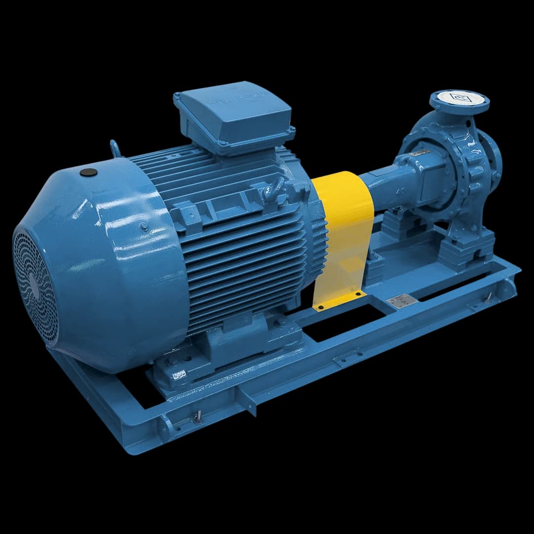
When a centrifugal pump starts and fails to establish flow, the cause is almost always one of these nine: (1) pump not primed — casing and suction line without liquid; (2) air ingress at the suction through gaskets, packing or connections; (3) foot valve stuck or with compromised sealing; (4) insufficient NPSHa — the installation does not supply the minimum inlet pressure the pump requires; (5) suction lift beyond what local atmospheric pressure can support — the theoretical ceiling is ~10.3 m of water column at sea level, and the practical limit is much lower; (6) clogged suction strainer, raising friction loss until suction becomes unfeasible; (7) reversed rotation direction — common after electrical maintenance; (8) worn, broken or over-clearanced impeller or wear ring; (9) dry packing drawing air through the stuffing box itself. In centrifugal pumps such as the FBCN, a correct start requires casing and suction filled with liquid, a tight suction, the discharge valve initially closed and rotation checked with the motor uncoupled. Never leave the pump running dry while you investigate.
At a glance
- Conventional centrifugal pumps such as the FBCN are not self-priming: the casing and the suction line must be full of liquid before startup.
- At sea level, the atmosphere supports at most about 10.3 m of cold-water column; after losses, vapor pressure and required NPSH are deducted, the practical suction limit is much lower.
- With reversed rotation, a centrifugal pump still builds some pressure, well below rated; on the FBCN, the correct direction is clockwise viewed from the drive end, checked with the motor uncoupled.
- Never run the pump dry, not even for a few seconds as a test: the mechanical seal, packing and wear rings depend on the liquid for lubrication and cooling.
- A radial centrifugal pump starts with the discharge closed, its lowest-power condition; positive displacement pumps such as the FBE and FBEI must never start against a closed discharge.
1. Pump not primed — the #1 cause
Conventional centrifugal pumps — including the whole FBCN line — are not self-priming. The impeller only transfers energy to the liquid when the casing and the suction line are completely full (down to the foot valve, when the installation has one). If there is an air pocket inside the casing, the impeller spins in air and cannot create the suction needed to draw liquid from the reservoir. The pumping sourcebook of the U.S.
Department of Energy (DOE) and the Hydraulic Institute sums up the rule: most centrifugal pumps are not self-priming and, once they lose prime, must be filled and vented before restarting.
The fix is the priming procedure: with the pump stopped, open the upper casing vent and fill with the pumped liquid itself (clean water, in a water pump) until it flows continuously from the vent with no bubbles. With flooded suction (pump below reservoir level), simply open the suction block valve and the vent until all air is purged.
With suction lift (pump above reservoir level), the line must be kept full — foot valve — or an auxiliary means is needed: elevated gravity priming tank, vacuum pump or ejector. In a thermal-oil circuit (FBOT line), filling follows the circuit procedure and uses the oil itself — never water.
Characteristic symptom of an unprimed start: the motor starts and reaches rated speed, current stays below normal (the impeller is moving only air) and the discharge gauge shows no pressure. Do not wait to "see if it primes": without liquid, the mechanical seal, packing and wear rings lose lubrication and can be damaged within seconds — shut down immediately and prime.
NEVER run the pump dry — not even for a few seconds as a test. A centrifugal pump is not designed to turn without liquid: mechanical seal faces and packing overheat and the wear rings lose their lubricating film. When in doubt, stop, prime and only then start.
2. Air ingress at suction
The suction line runs below atmospheric pressure whenever the pump sits above the reservoir level (and, even with flooded suction, when losses pull the inlet pressure down). Any sealing failure along that stretch — dried-out flange gasket, loose bolts, threaded joint without sealant, poorly tightened block-valve packing, cracked reducer sleeve — works as a hole through which air enters.
Air dilutes the pumped liquid, reduces flow, creates bubbling noise and, in severe cases, prevents suction entirely or makes the pump lose prime at every stop.
There are two safe field tests to locate air ingress. With the pump stopped, the hydrostatic one: fill the suction line with water and apply a low pressure within component limits (the head of an elevated tank or the supply network is usually enough), then look for drips at joints, connections and the stuffing box.
With the pump running and primed, cover the suspect joints with foam (shaving cream or soapy water): where air is entering, the foam is sucked in and dimples. Avoid pressurizing the line with compressed air — air stores energy and, if a joint or pipe ruptures, the release is violent; pneumatic testing only under an approved procedure.
The fix is to replace gaskets and packing, retighten to the correct torque, redo threads with a sealant compatible with the fluid (anaerobic or PTFE tape) and replace cracked parts. In critical systems, specifying flanged rather than threaded suction connections greatly reduces failure points.
3. Foot valve stuck or with compromised sealing
The foot valve is installed at the lower end of the suction piping, submerged in the reservoir. Its function is twofold: to filter coarse particles and — above all — to maintain the liquid column in the suction line when the pump stops, preventing prime loss. If the valve sticks open (object trapped between disc and seat), the column drains every time the pump shuts down, and the next startup fails.
If it sticks closed (corrosion, sediment), the pump starts but cannot draw the liquid.
Diagnosis: after priming and stopping the pump, wait 10 to 15 minutes with it off. If the next start requires re-priming, the column is draining — the foot valve is the main suspect, but confirm there is no leak at joints above it before replacing it. If the start never completes even with a fresh prime, the valve may be stuck closed or its strainer blocked — disassemble and inspect.
When specifying, prefer a foot valve with a removable strainer, which makes cleaning easier, in a material compatible with the fluid and the solids present (cast iron, bronze and stainless steel are the usual options).
4. Insufficient NPSHa and geometric height above physical limit
No pump "pulls" the liquid: it is the atmospheric pressure on the reservoir that pushes it into the suction. That is why there is a physical ceiling — about 10.3 m of water column at sea level.
In practice much less is left, because the liquid vapor pressure, the suction friction losses and the pump required NPSH must be deducted: Pumps & Systems, in a 2026 application article, treats about 7.6 m (25 ft) as the prudent boundary for cold water at sea level — still with a safety margin.
With hot water, volatile fluids or altitude, the limit drops: in Brasília, at about 1,170 m, atmospheric pressure is ~88 kPa and the theoretical ceiling falls to ~9 m.
The parameter that materializes this limit is NPSH (Net Positive Suction Head). If the NPSH available at the installation (NPSHa) is lower than the pump requirement (NPSHr, on the manufacturer curve), the pump cavitates or simply fails to establish flow.
The margin is not a fixed number of meters: ANSI/HI 9.6.1, from the Hydraulic Institute, expresses the margin as the ratio between NPSHa and the required NPSH and gives recommended values by application (chemical process, petroleum, water and wastewater, building services, general industry, among others).
In the 2024 edition, the reference became the manufacturer-stated NPSHr, which must be equal to or greater than the NPSH3 measured in test — the condition at which head drops 3%, which does not mean absence of cavitation. When NPSHa is insufficient: lower the pump (flooded suction), increase suction pipe diameter, reduce bends and valves, cool the fluid if possible or switch to a model with lower NPSHr.
A level-related case that often goes unnoticed is vortexing: when the liquid surface drops too close to the suction inlet, a whirlpool forms that carries air into the pump — and, in severe cases, it loses prime (the DOE/HI sourcebook describes exactly this mechanism). If the pump draws well with the tank full and fails near the minimum level, check the inlet submergence in that condition.
5. Clogged strainer and reversed rotation direction
The suction strainer clogs gradually as sediment, biofilm or leaves (in surface-water intakes) build up. The effect is higher suction friction loss, which reduces NPSHa until the pump stops drawing. Typical symptom: the pump runs normally for days or weeks, then flow drops gradually and finally it stops drawing. Diagnosis: measure the pressure before and after the strainer and compare with the clean-strainer reading recorded at commissioning.
On the suction side, every 0.1 bar of loss consumes about 1 m of NPSHa (0.1 bar ≈ 1.02 m of water column) — which is why the clogging limit of a suction strainer is much lower than that of a discharge filter and must be set from the installation NPSH margin.
Reversed rotation is a common cause after electrical maintenance: when the motor is replaced or the contactor rewired, two of the three phases can be swapped, and the motor spins backwards. A centrifugal pump turning the wrong way still builds some pressure — well below rated —, which misleads the diagnosis: flow drops sharply and abnormal noise appears.
Diagnosis: compare the actual direction, seen from the coupling side, with the arrow on the casing; on the FBCN, the correct direction is clockwise viewed from the drive end (FBCN technical manual). Fix: swap two phases at the motor terminal block — a job for a qualified electrician, with the circuit de-energized and locked out. Checking rotation with the motor uncoupled, before fitting the coupling, is the usual commissioning procedure, precisely so the pump never turns backwards or dry.
6. Worn impeller and dry packing aspirating air
An impeller worn by years of operation — especially with suspended solids or aggressive pH — loses efficiency at the vane edges, and the wear ring loses its original clearance. The result is a progressive drop in pressure and flow until the pump no longer overcomes the installation losses and seems "not to draw".
On the FBCN, the impeller is radial, single-suction, with a wear ring on the pressure side (except sizes 25-150, 32-125 and 32-125.1, according to the technical manual). Diagnosis: measure flow and head at a known point and compare with the pump curve. If, with priming, speed and suction already confirmed, the measured point falls clearly below the curve, impeller and wear-ring wear is the likely suspect — confirmation comes from disassembly, measuring the clearances.
Fix: replace impeller and wear ring with original parts and investigate the root cause (abrasion, corrosion, earlier cavitation).
Dry packing is a frequently forgotten cause of air ingress. In pumps with packing (rather than a mechanical seal), sealing depends on a small drip of liquid to lubricate and cool. If the packing was tightened more than necessary, or the pump stood idle long enough to dry out, the stuffing box starts drawing air through the very zone that should seal — the effect on suction is identical to a hole in the line.
Fix: readjust the gland gradually, with the pump running, a quarter turn at a time and a few minutes between adjustments, until the drip specified by the pump or packing manufacturer returns (the amount varies with sleeve diameter, pressure and temperature; packing that does not drip is dry).
Where drip is not acceptable, consider a mechanical seal — on the FBCN, the shaft has a protective sleeve in the sealing area and accepts packing or a mechanical seal (FBCN technical manual).
7. Correct startup procedure for a centrifugal pump
To avoid the nine causes above at the first start and afterwards, the usual commissioning sequence for a radial centrifugal pump such as the FBCN is: (1) check pump-motor alignment with a dial indicator before coupling — misalignment causes vibration and bearing wear; (2) check rotation direction with the motor uncoupled, against the arrow on the casing; (3) couple pump and motor and check the coupling axial gap; (4) prime — open the upper vent, fill casing and suction line and close the vent when liquid flows with no bubbles; (5) fully open the suction valve; (6) close the discharge valve; (7) start the motor; (8) as soon as the motor reaches rated speed, gradually open the discharge valve to the operating point — without keeping the pump long against a closed discharge, which heats the liquid; (9) check discharge pressure, motor current, bearing temperature and absence of abnormal vibration.
Starting against a closed discharge applies to radial centrifugal pumps because absorbed power is lowest at zero flow, which reduces the electrical stress on the motor (DOE/HI sourcebook); in axial pumps that relationship is reversed.
Caution: in positive displacement pumps, such as gear pumps (FBE and FBEI), the logic is the opposite — never start against a closed discharge. With downstream valves closed, pressure rises until the relief valve lifts, a fitting ruptures or the motor stalls; the FBEI MAN001-10 manual requires checking that all valves are fully open before starting and never closing them while the pump is running.
If, after the complete procedure, the pump still fails to establish flow, send FB Bombas application engineering the model and nameplate data, the fluid and temperature, the suction layout (drawing or photo) and the readings available — current, suction and discharge pressures and flow. Contact: comercial@fbbombas.com.br or WhatsApp +55 11 97287-4837.