

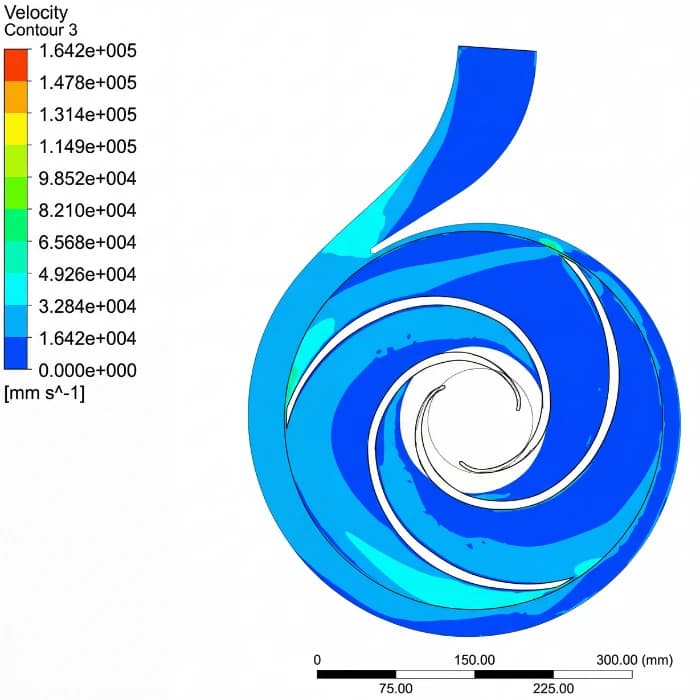
Measure flow, suction and discharge pressures, speed and fluid temperature. Calculate the head and compare it with the curve for the same configuration and test condition. A point below the curve can involve wear, air, cavitation, fluid properties, speed or measurement error; on its own, it does not identify the cause. Also check changes to valves, bypass and system losses before deciding on an intervention.
At a glance
- Pressure drop is a symptom, not a cause: diagnosis starts by measuring the Q×H point and overlaying it on the catalog curve.
- In Table 7 of the FBME service manual, insufficient head has eight causes, and six can be checked without dismantling the pump.
- Clearances and repair criteria depend on the configuration, with no guaranteed percentage recovery.
- Confirm liquid, speed and impeller diameter before comparing the point with the curve; the FBCN curve is for clean water at 20 °C.
- In a gear pump, delivered flow is theoretical flow minus slip, which decreases as viscosity rises.
1. The methodology: measure before intervening
Record the pressures at the suction and discharge points, flow, speed, temperature and the state of the valves. Instruments need suitable range, accuracy, installation and compatibility. When flow is estimated, state the method and its uncertainty; do not compare an estimate without context with the curve as if it were an acceptance test.
Check which curve corresponds to the impeller or gears, speed and liquid of the configuration. Shifts of the point guide hypotheses, not automatic conclusions. In a centrifugal pump, a lower speed or a change in viscosity changes the performance reference; in gear pumps, analyse actual flow, differential pressure, slip and inlet supply.
On the FBCN curve sheets, the header states that the values are for clean water at 20 °C, and each sheet shows a family of impeller diameters. On sheet CC-124.07, for the FBCN 65-315 at 1,750 rpm, the impellers range from 271 to 320 mm, and on every curve the head rises as flow decreases. Confirm the installed diameter before reading the point: comparing with the wrong diameter creates a loss that does not exist.
H = (Pd − Ps)/(ρg) + (Vd² − Vs²)/(2g) + Zd − Zs. Use pressure in Pa, density in kg/m³, velocities in m/s and elevations in m. Omit velocity and elevation terms only when measurement-point geometry justifies it.
2. Impeller wear and excessive ring clearances
Impeller wear or damage can change the curve, but its extent requires inspection and measurement. The approximate impeller-trim laws do not describe irregular erosion of vanes and passages. Record the geometry found and compare it with the manufacturer's reference, including the likely cause of the damage.
Clearances at the wear rings and internal surfaces influence recirculation and performance. Identify the components present in the configuration and their dimensional limits. There is no single 0.8 mm clearance or guaranteed 95% recovery for every FBCN. After a repair, confirm the agreed criterion and scope of performance verification.
The manuals show where the rings are. On the FBCN, the casing has a wear ring on the suction side, and the impeller has a wear ring on the pressure side, except for sizes 25-150, 32-125 and 32-125.1 (MTEC-03/00, items 2.1 and 2.2, p.7). The FBOT parts list includes the casing and impeller wear rings (parts 502 and 503; MTEC-16/00, p.8).
In the FBME service manual, worn rings are a cause of insufficient flow, and the solution is to replace them (item 29, p.22). The U.S. Department of Energy guide produced with the Hydraulic Institute lists excessive wear-ring clearances among the causes of inefficient operation (p.14) and places wear rings and impellers among the repair items that typically have to be replaced regularly (p.34).
3. Recurring partial cavitation
Assess the suction with the current absolute pressure, level, temperature and losses. When the curve gives NPSH3, it uses a head-drop criterion in the test and does not represent the absence of cavitation. The required margin depends on the application and must be defined with the technical reference and the manufacturer.
Noise, vibration and loss of performance can accompany cavitation, but also other anomalies. Compare changes in temperature, level, filter and piping with the history. The diagnosis must not depend on a fixed percentage of head loss or on an isolated frequency.
In the FBME service manual, the suction side gathers several causes of insufficient flow: suction lift too high (item 3: check the NPSH and change the suction lift), insufficient NPSH (item 4: reduce the suction lift), an undersized or blocked foot valve (items 9 and 10) and insufficient submergence of the suction pipe (item 11). None of them requires opening the pump.
When the curve gives NPSH3, it is the NPSH at which the test records a 3% drop in head, according to the Hydraulic Institute. With the suction at that point, the pump already delivers less head than the curve, even without wear.
4. External bypass, suction air and clogged strainer
Check the function and position of the bypass in the design. Compare the total pump flow with the flow that reaches the process and the flow that returns. A return may be intentional, for control or protection; its presence does not prove a fault, and its adjustment must respect the minimum flow and the facility procedure.
The FBME service manual separates the ways air and gas get in: excess air or gas in the liquid and air pockets in the suction line (items 5 and 6: change the piping layout and, if necessary, install a vent line), a poorly sealed suction pipe (item 7) and air entering through the packing (item 8).
For air entering through the packing, the manual says to tighten the gland, replace the packing or clear the seal lubrication channel. In Table 7, excess air or gas is a cause of both insufficient flow and insufficient head, and pressure fluctuation alone does not separate this cause from the others.
An obstruction downstream of the pump is another case. According to the Hydraulic Institute, the system operates where the pump curve crosses the system curve, and closing a valve adds resistance over the entire range of flows; any component that obstructs the flow adds loss. In a centrifugal pump, a partially blocked strainer, heat exchanger, control valve or nozzle moves the point to the left on the curve: less flow and more head.
That is why a discharge pressure that rose while the process flow fell is the opposite of a pump pressure loss and points first to the system. Only a complete measurement, with flow and pressures on both sides, separates the two cases.
5. Altered viscosity and motor speed drop
In centrifugal pumps, the viscosity correction depends on flow, head, speed and liquid properties; there is no fixed head reduction for 50, 200 or 500 cP. In gear pumps, viscosity influences slip, friction and filling. Use the configuration's performance data and inlet conditions to assess the change.
The Hydraulic Institute describes the effect on a centrifugal pump: with a viscous liquid, head and flow fall and power rises compared with the water test, and the correction follows ANSI/HI 9.6.7. In the FBME service manual, viscosity different from the design value is a cause of insufficient head, and the solution is to adjust the pump to a point compatible with the liquid or change the impeller diameter (item 20, p.22).
In a gear pump, theoretical flow is proportional to speed, and the difference to the delivered flow is slip, which depends on viscosity and pressure (Hydraulic Institute). Since higher viscosity reduces slip, a liquid less viscous than expected tends to increase it and reduce the delivered flow.
On the FBE, the recommended speed falls with viscosity, from 1,750 rpm between 30 and 250 SSU to 300 to 150 rpm between 50,000 and 100,000 SSU (FBE catalog 2026, p.5). Compare the measured speed and the viscosity at pumping temperature with those of the selection before suspecting wear.
Measure the speed and check the drive and transmission. For homologous points of a centrifugal pump under similarity conditions, head varies approximately with the square of speed; the system point still depends on its own curve. Do not attribute a speed loss only to the motor's age, nor use the approximation to diagnose an electrical fault.
6. FB Bombas decision tree
Order the hypotheses by evidence: validate the instruments and configuration data; check speed and liquid; examine changes in the system; assess the suction and, when indicated, the mechanical condition. An intermittent drop does not prove air ingress, just as a point below the curve does not prove wear. Leak-tightness or pressure tests require a specific procedure and the limits of the components.
The table reproduces, from the FBME service manual, the eight causes of insufficient head and the solution given for each. Six can be checked with the pump assembled: air, speed, direction of rotation, required head, viscosity and parallel operation. Impeller and gaskets require disassembly. Item 31 is specific to multistage construction; the FBCN, a single-stage pump as its curve sheets show, has no gaskets between stages.
| Item | Cause | Solution given in the manual |
|---|---|---|
| 5 | Excess air or gas in the liquid | Change the piping layout; if necessary, install a vent line |
| 14 | Speed too low | Increase the speed |
| 16 | Wrong direction of rotation | Swap one of the phases of the motor cable |
| 17 | Installation head requirement higher than the pump head | Fit an impeller with a larger diameter |
| 20 | Liquid viscosity different from the design value | Adjust the pump to a point compatible with the liquid or fit a larger or smaller impeller |
| 22 | Pump not suited to parallel operation | Adapt the piping layout |
| 30 | Damaged impeller | Replace the impeller and its accessories |
| 31 | Defective gaskets on the discharge, suction and stage casings, allowing internal leakage | Replace the gaskets |
Send the assembly identification, the reference curve and the measurements with operating conditions to FB Bombas engineering. Confirm the scope of support and of any tests in the enquiry: comercial@fbbombas.com.br or WhatsApp +55 11 97287-4837.