


FB Bombas Engineering Team21 min read
Start from the largest simultaneous demand in the hydraulic design (hydrants, sprinklers or both, per the local rule) and calculate total head to the most demanding point. Select the pump so that this demand does not exceed 150% of rated flow, then check the NFPA 20 envelope: at least 65% of rated pressure at 150% of rated flow and shutoff no higher than 140%. Then verify NPSH, driver, diesel tank and jockey pump.
FB pump for this application
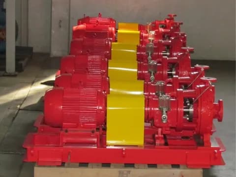
FBFS
Do you already have the design flow and pressure?
FBFS sets carry an FBCN main pump, a jockey pump, a control panel and a base, with electric, diesel or electric plus diesel drive, designed to NFPA 20 and NBR 16704.
Source: FBFS
At a glance
- Design flow is the largest simultaneous demand in the hydraulic design under the local rule; the pump is selected so that this demand does not exceed 150% of rated flow.
- NFPA 20 requires the main pump to deliver at least 65% of rated pressure at 150% of rated flow, with shutoff no higher than 140% of rated pressure.
- With positive suction, suction-flange pressure at 150% of flow must be 0 psi or higher; in São Paulo, IT 22 accepts suction lift only for types 1 to 3, with NPSH calculated at 1.5 times the system's rated flow.
- With a diesel engine, NFPA 20 sizes the tank for 12 hours of the engine manufacturer's published consumption, plus 5% for expansion and 5% for the sump; São Paulo's IT 22 requires twice the duration of the water reserve.
- The jockey pump makes up allowable leakage; the NFPA 20 annex suggests replacing it in 10 minutes, or 1 gpm, whichever is larger. The 1% of main-pump flow rule does not come from the standard.
Three hypothetical numerical examples show the full calculation, from the rated point to the 150% point.
1. Overview: what sizing requires
Sizing a fire pump is not a matter of picking a catalogue model by flow. NFPA 20 sets requirements across the whole main-pump curve, from zero flow (shutoff) to 150% of rated flow, and the package also involves suction, driver, controller and, where the network needs one, a jockey pump to hold pressure.
In Brazil, minimum flow and pressure come from the state rule, the fire department's technical instruction, and from the approved design; in other countries, the code adopted by the authority having jurisdiction plays that role. That is why the sequence starts with the demand and ends with the measured curve of the selected equipment.
- Step 1. Design flow: the largest simultaneous demand in the design (hydrants, hose reels, sprinklers or the sum the local rule requires)
- Step 2. Total head: elevation + friction losses (Hazen-Williams) + residual pressure at the most demanding point
- Step 3. Suction: available NPSH at minimum water level and suction-flange pressure checked at 150% of rated flow
- Step 4. Main pump: a rated flow that covers the demand up to 150% and a curve inside the NFPA 20 envelope
- Step 5. Driver: electric, diesel or both, with a reliable power source and a fuel tank sized from engine consumption
- Step 6. Jockey pump: flow to make up allowable leakage and start and stop pressures staggered with the main pump
Note
FB Bombas builds FBFS packages with an FBCN main pump in three configurations: electric, diesel or electric + diesel, each with jockey pump, controllers and base. For selection, send the hydraulic design (required flow and pressure), suction data (reservoir type, minimum level and elevation difference), the location and the adopted standards. The documentation for each supply is defined in the proposal.
2. Step 1: Calculate design flow
Design flow is the largest demand the hydraulic design places on the pump at the same time. For hydrants, it follows from the number of jets operating together and the minimum flow of each: São Paulo's IT 22, for example, requires the two most demanding jets, each with at least the flow in its Table 2. For sprinklers, it comes from the hydraulic calculation of the design area, using the density required over that area.
Systems are added together only when the local rule says so, and stored water volume is a different quantity: it does not enter the flow.
With the demand in hand, the NFPA 20 selection rule applies: the largest demand of any system connected to the pump must not exceed 150% of rated flow, and applying the pump at flows below 90% of rated capacity is not recommended. Rated flow therefore falls between the demand divided by 1.5 and the demand divided by 0.9.
For a demand of 1,500 L/min, that gives a window from 1,000 to about 1,670 L/min, and the choice within it depends on the curve, suction and power. NFPA 20 lists typical rated capacities from 25 to 5,000 gpm, about 95 to 18,900 L/min.
Scroll the table to see every column. The first column stays on the left.
| System and rule | Published criterion | Calculation | Minimum demand |
|---|---|---|---|
| Type 2 hydrants — IT 22 (São Paulo) | 150 L/min and 30 m of water at the most demanding valve; two simultaneous jets | 2 × 150 L/min | 300 L/min |
| Type 3 hydrants — IT 22 (São Paulo) | 200 L/min and 40 m of water; two simultaneous jets | 2 × 200 L/min | 400 L/min |
| Type 4 hydrants, DN40 hose — IT 22 (São Paulo) | 300 L/min and 65 m of water; two simultaneous jets | 2 × 300 L/min | 600 L/min |
| Type 4 hydrants, DN65 hose — IT 22 (São Paulo) | 300 L/min and 30 m of water; two simultaneous jets | 2 × 300 L/min | 600 L/min |
| Type 5 hydrants — IT 22 (São Paulo) | 600 L/min and 60 m of water; double-outlet hydrant, two simultaneous jets | 2 × 600 L/min | 1,200 L/min |
| Sprinklers, light hazard — NT 13/2021 (Federal District) | 30 min of operation; 25,000 L reserve when not set by calculation | 25,000 L ÷ 30 min | ≈ 833 L/min (average) |
| Sprinklers, ordinary hazard I — NT 13/2021 (Federal District) | 60 min; 91,000 L | 91,000 L ÷ 60 min | ≈ 1,517 L/min (average) |
| Sprinklers, ordinary hazard II — NT 13/2021 (Federal District) | 60 min; 136,500 L | 136,500 L ÷ 60 min | ≈ 2,275 L/min (average) |
| Sprinklers, extra hazard I — NT 13/2021 (Federal District) | 90 min; 341,000 L | 341,000 L ÷ 90 min | ≈ 3,789 L/min (average) |
| Sprinklers, extra hazard II — NT 13/2021 (Federal District) | 90 min; 515,000 L | 515,000 L ÷ 90 min | ≈ 5,722 L/min (average) |
Warning
These figures apply to the jurisdictions cited and serve as an order of magnitude. For hydrants, the second jet is hydraulically more favourable, receives more pressure and discharges more than the minimum, so the real flow comes from the hydraulic calculation. For sprinklers, dividing volume by time only shows the average flow the table reserve can sustain; pump flow comes from the design-area calculation. Each Brazilian state publishes its own rule (in Goiás, for example, NT 22/2025 covers hydrants), and flammable-liquid tank farms add foam and cooling water under their own standards, such as NBR 17505 and NFPA 11.
3. Step 2: Calculate required pressure (total dynamic head)
Total dynamic head (TDH) is the energy balance between the water at its source and the most demanding point. For an open reservoir with negligible velocities, it reduces to three terms: TDH = Hgeo + Hf + Hres, where Hgeo is the elevation from the water level to the highest point served, Hf is the friction and minor losses up to that point and Hres is the residual pressure required there.
If the water arrives under pressure, from the public main or an elevated tank, that pressure is subtracted. Work everything in metres of water column: 1 bar is about 10.2 m of water.
Residual pressure comes from the rule of each system. For hydrants under São Paulo's IT 22, it is the minimum pressure at the most demanding hydrant valve (30 m of water for type 2, 40 m for type 3, 60 m for type 5), and maximum working pressure at the nozzles must not exceed 100 m of water.
For sprinklers, NFPA 13 sets 7 psi (0.5 bar) as the minimum operating pressure of any sprinkler, but the design value comes from the required flow and the sprinkler K-factor, through Q = K × √p. A K80 sprinkler (K5.6 in US units) discharges 80 L/min at 1 bar; to deliver 100 L/min, it needs (100/80)² ≈ 1.56 bar.
Friction loss in fire networks is usually calculated with Hazen-Williams, using the formula below, valid for water. The C coefficient depends on the material: São Paulo’s IT 22 (Table 1) uses 100 for black steel in dry systems and unlined cast iron, 120 for black steel in wet systems and galvanized steel, 140 for cement-lined cast iron and 150 for copper and plastic, always for new pipe.
IT 22 also limits velocity to 5 m/s in the network and 3 m/s in positive suction (2 m/s in suction lift). Minor losses enter as equivalent length or as a K coefficient; the care point is not to count the same fitting twice.
Hf = 10,67 × (Q^1,852 / (C^1,852 × D^4,87)) × L

Hf = perda de carga (m)
Q  = vazão (m³/s)
C  = coeficiente de rugosidade Hazen-Williams
D  = diâmetro interno (m)
L  = comprimento equivalente (m)
Hazen-Williams equation for friction loss in fire piping (water, turbulent regime):
Engineering note
Worked example: 1,500 L/min (0.025 m³/s) in DN100 galvanized steel pipe, 102.3 mm internal diameter (schedule 40) and C = 120, over 120 m of equivalent length, loses about 12.9 m, at a velocity of 3.0 m/s, within the limit. With C = 100, the same run would lose 18.1 m, 40% more, because loss varies with C raised to −1.852. In DN80, the loss would rise to about 49 m and velocity to 5.2 m/s, above the 5 m/s limit. Since loss grows with flow raised to 1.852, at 150% of flow the same run loses about 2.1 times its value at rated flow.
4. Step 3: Check suction and available NPSH
NFPA 20 does not accept a horizontal centrifugal pump with suction lift: when water has to be raised from a level below the pump, the solution the standard provides is a vertical turbine pump. With positive suction, the suction piping must be sized so that, with the pump at 150% of rated flow, gauge pressure at the suction flange is 0 psi or higher.
If suction comes from a tank installed at or above pump level, down to −3 psi (−0.2 bar) is allowed at the flange, checked at the lowest level, after the maximum demand has been supplied for the required duration.
São Paulo's IT 22 is more flexible and sets the limit in numbers. The pump is under positive suction when its shaft is below the reference water level; the shaft may sit up to 2 m above that level, or at 1/3 of the effective reservoir capacity, whichever is less, and beyond that suction is considered negative.
Suction lift is accepted only for system types 1, 2 and 3, with a dedicated suction pipe, a foot valve with strainer, means of keeping the suction always full and a priming tank of at least 100 L (type 1) or 200 L (types 2 and 3). In that case, available NPSH must be calculated at 1.5 times the system's rated flow and be greater than or equal to the NPSH required by the pump.
For an open reservoir, NPSHa = Patm + Hz − Hf,s − Pv, with every term in metres of liquid. Patm is local atmospheric pressure: about 10.3 m at sea level and 9.2 m at 1,000 m altitude, per the standard atmosphere. Hz is the elevation between the minimum water level and the pump shaft, positive with flooded suction.
Hf,s is the suction friction loss, and Pv is the vapour pressure of water, 0.24 m at 20 °C and 0.32 m at 25 °C.
Engineering note
Example: at sea level, with water at 25 °C, minimum level 1.5 m above the shaft and 1.2 m of suction loss at 150% of flow, NPSHa ≈ 10.3 + 1.5 − 1.2 − 0.3 ≈ 10.3 m. Compare it with the pump NPSHr at that same flow, which is the most demanding point of the curve. Do not treat NPSHa = NPSHr as a safe condition: catalogue NPSHr (NPSH3) is measured when pump head has already dropped 3%. That is why ANSI/HI 9.6.1 expresses margin as the NPSHa/NPSHr ratio, with values that vary by application.
5. Step 4: The characteristic curve required by NFPA 20
This is the step that separates a fire pump from a general-service pump. NFPA 20 requires three points on the main-pump curve: at rated flow, at least rated pressure; at 150% of rated flow, at least 65% of rated pressure; and, with the valve closed (shutoff), no more than 140% of rated pressure. The 150% point guarantees a performance reserve if real demand exceeds the design.
The shutoff limit protects the network and components from the highest pressure the pump produces when every outlet is closed.
That envelope calls for a relatively flat curve. An impeller that rises too much at shutoff goes beyond 140%, and one that falls too much after the rated point does not reach 65% at 150%. That is why selection is made from the test curve of the pump, impeller diameter and speed combination, not from the catalogue rated point.
Check absorbed power up to 150%: with radial impellers, power grows with flow, and the highest draw appears on the right side of the curve. In São Paulo, IT 22 does not recommend fire pumps with pressure above 100 m of water and requires, for electric pumps above 600 L/min, a continuous water flow through a 6 mm tube or orifice plate, to avoid overheating at zero flow.
Scroll the table to see every column. The first column stays on the left.
| Operating point | Flow (% of rated) | Required pressure | Why it exists |
|---|---|---|---|
| Shutoff (closed valve) | 0% | No more than 140% of rated pressure | Limits the pressure the network, valves and fittings receive with every outlet closed |
| Rated point | 100% | At least 100% of rated pressure | It is the design point that meets the hydraulic design |
| Overload | 150% | At least 65% of rated pressure | It is the largest demand NFPA 20 allows on the pump and the point where suction, NPSH and power are checked |
Warning
That is why choosing a centrifugal pump from the catalogue rated point alone is not enough for a system designed to NFPA 20: the whole curve must fit the envelope, and that depends on impeller profile, impeller diameter and speed. At its factory in Cabreúva-SP, FB Bombas performs CNC machining and assembly. For an FBCN fire pump, request the curve of the proposed combination (pump, impeller and speed), with the three envelope points and the power at each one. The documentation for each supply is defined in the proposal; the series catalogue does not replace the record of the selected assembly.
6. Step 5: Define the driver and the diesel tank
NFPA 20 does not impose diesel by building type. It accepts an electric pump connected to a reliable power source and requires at least one alternate source, such as an on-site generator, when the normal supply cannot be considered reliable; a standby pump with a diesel engine removes the need for that alternate source.
When the diesel pump is the backup for the electric one, it must meet the same demand on its own, with the same flow, pressure and curve envelope. What diesel changes is the set of engine requirements: fuel, batteries, cooling, ventilation and exhaust.
In São Paulo, IT 22 details the driver in its Annex C. The pump's electrical supply must be independent of the general load, so that the building can be switched off without stopping the pump, and, if utility power fails, the electric pump may be fed by a diesel generator. The pump must reach full speed in about 30 s, and the electric motor must accelerate in no more than 10 s.
Once started, it stops only manually, at the pump-room panel. With a combustion engine, the set must run for 6 h uninterrupted at full load, the governor holds rated speed within a 10% tolerance, the batteries float on a dual charger and, if there is a single combustion-driven pump, starting must be automatic.
The fuel tank is where the two rules differ most. NFPA 20 sizes it from the fuel consumption published by the engine manufacturer: at least 12 hours of operation, plus 5% of volume for expansion and 5% for the tank sump, below the fuel suction connection. When the engine’s fuel consumption is not known, the tank must hold at least 1 gal/hp (5.07 L/kW), plus the same 5% and 5%.
São Paulo's IT 22 requires fuel to keep the set at full load for at least twice the operating time of the water reserve, with a containment basin of 1.5 times the tank capacity and a separate tank for each engine.
Engineering note
Example with a hypothetical engine that burns 20 L/h at full load: under NFPA 20, 20 × 12 = 240 L, plus 10%, gives 264 L. In São Paulo, with a water reserve that lasts 60 min at pump flow, the minimum would be 2 × 1 h × 20 L/h = 40 L. If the contract requires NFPA 20 and the site is in São Paulo, the tank must meet both rules, which in practice means the 12-hour one. Always use the consumption on the data sheet of the selected engine, not a generic value.
7. Step 6: Size the jockey pump
A jockey pump is a small pump that keeps the network pressurized and makes up small losses, such as a drip from a joint or a valve, so that the main pump starts only when there is fire demand. It does not fight fire and is not part of the design flow. NFPA 20 requires it to replace the pressure lost through allowable leakage and normal drops, with a rated capacity not less than the normal leakage rate.
The annex of the standard suggests sizing it to make up the allowable leakage in 10 minutes, or 1 gpm (3.8 L/min), whichever is larger. The rule of 1% of main-pump flow, common in the market, does not come from the standard.
In São Paulo, IT 22 requires a jockey pump when the hydrant or hose-reel network has more than six outlets, except when the fire reservoir is elevated, and limits its flow to 20 L/min. The maximum operating pressure of the jockey must equal the shutoff pressure of the main pump, and the IT recommends about 10 m of water (100 kPa) between the sequential starts of the pumps.
Automation is done with pressure switches: the jockey starts and stops on its own, and the main pump only starts automatically. The NFPA 20 annex suggests this pressure staging:
- Jockey stop: main-pump shutoff (churn) pressure plus the minimum static suction pressure
- Jockey start: at least 10 psi (0.69 bar, about 7 m of water) below the stop point
- Main-pump start: 10 psi (0.69 bar, about 7 m of water) below the jockey start
- Each additional pump: a further 10 psi (0.69 bar) below the previous one; where minimum run times are provided, the pump keeps running after these pressures are reached
Engineering note
Example with hypothetical numbers: main pump with 8.0 bar shutoff and a reservoir that guarantees 0.3 bar static at suction. The jockey stops at 8.3 bar and starts at 7.6 bar; the main pump starts at 6.9 bar; a second pump would start at 6.2 bar. Check that the network and components withstand the jockey stop pressure and that normal network pressure stays comfortably above the main-pump start, to avoid nuisance starts. In São Paulo, where the main pump stops only manually, each nuisance start means a trip to the pump room.
8. Three numerical examples: from total head to the curve envelope
Scenarios A, B and C are hypothetical: flows and terms were chosen to show the calculation and do not represent FB Bombas projects or the requirements of any standard. For each one, the table adds the head terms, applies the NFPA 20 envelope to the rated point and shows the hydraulic power (ρ·g·Q·H). Shaft power is that value divided by the pump efficiency read on the curve.
Look at scenario B: with 45 m of elevation, a curve with shutoff at the 140% limit would reach 105 m. Since São Paulo's IT 22 does not recommend fire pumps with pressure above 100 m of water and limits nozzle working pressure to 100 m of water, this case calls for a flatter curve, use of the available suction pressure or splitting the network into zones, a decision that belongs to the designer.
Scroll the table to see every column. The first column stays on the left.
| Item | Scenario A | Scenario B | Scenario C |
|---|---|---|---|
| Hypothetical rated flow | 2,700 L/min | 1,700 L/min | 4,000 L/min |
| Elevation | 20 m | 45 m | 12 m |
| Estimated friction loss | 25 m | 20 m | 35 m |
| Assumed residual pressure | 10 m | 10 m | 10 m |
| TDH at the rated point | 55 m | 75 m | 57 m |
| 150% point the curve must meet | 4,050 L/min at ≥ 35.8 m | 2,550 L/min at ≥ 48.8 m | 6,000 L/min at ≥ 37.1 m |
| Maximum shutoff under NFPA 20 (140%) | ≤ 77 m | ≤ 105 m | ≤ 79.8 m |
| Hydraulic power at the rated point (ρ·g·Q·H) | 24.3 kW | 20.8 kW | 37.3 kW |
9. Final checklist before buying
Before closing the purchase, compare proposals against the same hydraulic design, standard and acceptance criteria, and confirm with the manufacturer and the designer:
- Curve of the proposed combination (pump, impeller and speed), with shutoff, rated point and 150%, and power at each point
- Applied tolerances and documents delivered with the equipment
- Controller dedicated to the fire pump and electrical supply independent of the building general load
- Direct flexible coupling, with no belts or chains, and an isolating valve at suction plus check and isolating valves at discharge, as São Paulo's IT 22 requires
- NPSHa calculated at minimum water level and 150% of flow, with the ANSI/HI 9.6.1 margin
- Alignment checked on the final foundation, after the piping is connected and the anchor bolts are tightened
- Back-pull-out construction, as on the FBCN: the rotating assembly comes out for maintenance without dismantling the suction and discharge piping
- Technical manual in Portuguese, characteristic curve and recommended spare parts list
- Warranty, technical support and parts defined in the proposal
Key point
To start the selection, send FB Bombas the hydraulic design (required flow and pressure), the system type (hydrants, sprinklers or both), suction data (reservoir, minimum level and elevation difference), site altitude, the intended driver (electric, diesel or both) and the standard required by the design, the local authority or the insurer. Contact: comercial@fbbombas.com.br or WhatsApp +55 11 97287-4837.