

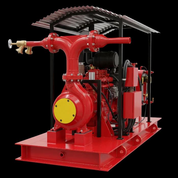
A fire water reserve (RTI) is the water volume dedicated exclusively to firefighting, in a dedicated tank or a shared one with the effective capacity preserved. NBR 13714 calculates it as V = Q × t: the flow of two outlets from Table 1 of the standard, for 60 minutes in type 1 and 2 systems or 30 minutes in type 3. State Technical Instructions may tabulate the volume, and sprinklers have their own reserve. Only the water above level X counts, and the pump suction depends on that level. FB Bombas specifies the pump set from the tank elevations and the design demand.
At a glance
- The fire water reserve (RTI) is the water volume dedicated exclusively to firefighting; NBR 13714 provides it for first response, over a set time.
- For hydrants and hose reels, V = Q × t: the flow of two outlets from Table 1 and 60 minutes for types 1 and 2 or 30 minutes for type 3, from 9,600 to 54,000 litres.
- Technical Instructions may tabulate the reserve: in São Paulo’s IT 22, from 5 m³ to 180 m³ by area and occupancy; sprinklers have their own reserve.
- Only the effective capacity counts: the water between the normal level and level X, the lowest before a vortex forms with the main pump at full load.
- Positive suction is preferred: pump shaft below level X, allowed up to 2 m above it or at 1/3 of the effective capacity, whichever is less.
1. What the fire water reserve is and why it exists
NBR 13714, the Brazilian standard for hydrant and hose-reel systems, defines the fire reserve in one line: the water volume dedicated exclusively to firefighting. Fire Department Technical Instructions call it the technical fire reserve, RTI; São Paulo’s IT 22, for example, uses the abbreviation for the volumes in its Table 3. The standard provides the reserve for first response, over a set time.
After that time, the standard says, the nearest Fire Department is considered to take over, using the public network, tanker trucks or natural sources. The time therefore comes from the standard or the Technical Instruction, not from an estimate of fire-engine arrival. And the reserve is not the building water tank: it may share the same tank, but consumption cannot reach it, and the effective capacity must be maintained permanently.
2. How to calculate: V = Q × t, with the flow of two outlets
For any hydrant or hose-reel system, NBR 13714 gives the minimum reserve volume as V = Q × t. Q is the flow of two system outlets, at the per-outlet values of Table 1 of the standard: 80 or 100 L/min for type 1 (hose reels), 300 L/min for type 2 and 900 L/min for type 3. And t is the time: 60 minutes for types 1 and 2 and 30 minutes for type 3.
For hydraulic sizing, the same standard considers the simultaneous use of the two hydraulically most unfavorable jets, at no less than the Table 1 flows. Applied to the three types, the formula gives the volumes in the table below. These are the standard’s minimums; the state Technical Instruction may set a different volume. And the design-report rule applies: sizing parameters, tables and tools are listed in it, with no reference to another project.
V [litros] = Q [L/min] × t [min]Minimum fire reserve volume for hydrants and hose reels under NBR 13714: Q in L/min (two outlets, Table 1), t in minutes (60 min for types 1 and 2; 30 min for type 3)
| System type | Flow per outlet (Table 1) | Q (2 outlets) | Time t | Minimum volume V |
|---|---|---|---|---|
| Type 1 (hose reels) | 80 or 100 L/min | 160 or 200 L/min | 60 min | 9,600 or 12,000 L |
| Type 2 (hydrants, 40 mm hose) | 300 L/min | 600 L/min | 60 min | 36,000 L |
| Type 3 (hydrants, 65 mm hose) | 900 L/min | 1,800 L/min | 30 min | 54,000 L |
NBR 13714 does not allow other fire protection systems to be fed through interconnected piping, except type 1, which may be interconnected with properly sized automatic sprinklers. In São Paulo, IT 22 allows the interconnection provided it meets the parameters of IT 23, on automatic sprinklers.
3. State instructions and sprinklers: when the reserve comes from a table
State rules may tabulate the reserve instead of calculating it. São Paulo’s IT 22 defines five system types and sets, in its Table 3, the minimum reserve by built area and occupancy classification: from 5 m³ (type 1, up to 2,500 m²) to 180 m³ (type 5, above 50,000 m²). Goiás NT 22 also refers the reserve to its own Table 3, by built area and occupancy.
The Technical Instruction types are not those of NBR 13714. In IT 22, the minimum flow at the valve of the most unfavorable hydrant ranges from 100 L/min for type 1 to 600 L/min for type 5, the latter with a double outlet. That is why the formula of one document is not combined with the table of another, nor is another state’s table used as a shortcut: the edition in force in the facility’s jurisdiction applies.
Sprinklers have their own reserve. In the CBMDF NT 13, the minimum operating time is 30 minutes for light hazard, 60 minutes for ordinary hazard I and II and 90 minutes for extra hazard I and II. When the reserve is not defined by calculation, the standard tabulates the volume for spray sprinklers, from 25,000 litres for light hazard to 515,000 litres for extra hazard II. With hydrants and sprinklers, the design documents how the demands combine.
4. Total volume is not effective capacity: level X, vortex and shared tanks
The first point is not to count the total tank volume as the reserve. NBR 13714 works with effective capacity: the height between the normal water level and level X, the lowest level before a vortex forms with the main pump at full load. Below level X there is still water in the tank, but it does not count toward the reserve.
Level X comes from the suction geometry. Table A.1 of the standard gives the minimum dimensions A and B of the suction pit by the nominal diameter of the suction pipe, and level X is determined by dimension A: 250 mm for DN 65, 370 mm for DN 100 and 750 mm for DN 250. With an anti-vortex device on the suction pipe, the standard allows dimension A to be disregarded, except for the side intake of figure A.2.
Whenever possible, the tank has a suction pit with the minimum dimensions of Table A.1. São Paulo’s IT 22 adds that, without a pit, dimensions A and B are still provided and left out of the reserve, and it accepts as an alternative an inlet facing the bottom, with an anti-vortex plate, at least twice the pipe diameter and at least 150 mm above the bottom.
A tank shared with building consumption is allowed when the other-use outlets preserve the effective capacity. NBR 13714 also requires cleaning without fully interrupting supply, keeping at least 50% of the reserve in two interconnected cells; a tank closed against light and foreign material; independent drain and overflow; and, as a recommendation, replenishment at 1 L/min per cubic meter of reserve.
5. What the reserve requires from the fire pump
The reserve position defines the supply. An elevated tank may feed the system by gravity if its height delivers the minimum flows and pressures at the most unfavorable hydrants or hose reels; if it does not, NBR 13714 calls for a booster pump in bypass. A ground-level, semi-buried or underground tank requires fixed, automatically started pumps in the pump room.
The preferred condition is positive suction: the pump shaft line below level X. The standard allows the shaft up to 2 m above level X, or at 1/3 of the tank effective capacity, whichever is less; beyond that, the suction is considered negative, and the main pump carries a compound gauge on the suction, besides the discharge pressure gauge. In the suction pipe, water velocity does not exceed 4 m/s.
With negative suction, São Paulo’s IT 22 requires the available NPSH to be calculated at 1.5 times the system rated flow and kept greater than or equal to the NPSH required by the pump. Annex B of NBR 13714 completes the set: automatic start on the simple opening of any hydrant, full speed in approximately 30 seconds, manual-only shutdown at the pump-room panel and access all around the pumps.
Reserve and pump room are one design: the tank defines the suction elevation, the suction defines the pump, and the pump defines the room. For selection, provide the normal and X levels of the tank, the elevations, the suction drawing and the design demand.
The standard prefers positive suction and only allows the shaft above level X within the limit of 2 m or 1/3 of the effective capacity. If the layout allows, flood the pump: lower the pump room or raise the tank, instead of relying on priming.
6. Common mistakes with the fire water reserve
Four mistakes show up in specifications. First: declaring the total tank volume as the reserve, without discounting building consumption and the water below level X. Second: calculating only the hydrant reserve and forgetting the sprinkler reserve in buildings with both systems. Third: sharing the tank without positioning the consumption outlets to preserve the effective capacity. Fourth: placing the tank far from or below the pump room and pushing the pump into negative suction.
The sequence that avoids rework: system type and reserve per the jurisdiction’s Technical Instruction and NBR 13714; effective capacity checked against the suction pit geometry; pump elevation with positive suction; and only then the pump set specification. FB Bombas application engineering receives elevations, volumes, pump room position and design demand and confirms the selection and the supply components, such as main pump, jockey and panel.
Reserve calculation, fire protection design and approval remain with the facility’s responsible engineers. NBR 13714 itself requires design, installation, tests and maintenance to be carried out by legally qualified companies or professionals.