


FB Bombas Engineering Team5 min read
The impeller transfers shaft work to the liquid, increasing its energy. The casing can convert part of velocity energy into pressure. Total gain is pump head, and actual duty depends on pump and system curves. FBCN presents mechanical construction to ASME B73.1 and back-pull-out; range limits do not apply to every model or simultaneously.
FB Bombas pump for this application
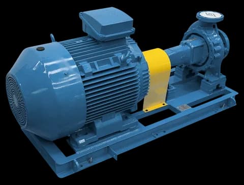
FBCN Series
Looking for a normalized centrifugal pump?
The FBCN is the FB Bombas normalized centrifugal pump for water and low-viscosity liquids, mechanically conforming to ASME B73.1.
Source: manual FBCN MTEC-03/00, p.1
At a glance
- A centrifugal pump transfers motor energy to the liquid through an impeller spinning inside a spiral volute.
- Velocity and pressure change in impeller and casing; actual head includes loss effects.
- The Euler equation governs theoretical head, linking impeller tangential velocity to the fluid tangential component.
- The FBCN Series gathers 54 centrifugal models with flow up to 2,200 m³/h and head up to 135 m.
- Use configuration curves and documents for selection.
How the impeller converts mechanical energy into pressure energy, role of the volute, simplified Euler equation and references to FB Bombas FBCN pumps per ASME B73.1.
1. What is a centrifugal pump
A centrifugal pump is a hydraulic turbomachine that converts mechanical shaft work (delivered by an electric or diesel motor) into useful hydraulic energy to move liquid against installation resistance.
Unlike positive displacement pumps — such as the FBE external gear series — the centrifugal pump does not displace a fixed volume per revolution; it imposes a centrifugal field on the fluid whose intensity depends on the impeller speed and outlet diameter.
Centrifugal selection considers liquid and curve as well as materials, sealing and suction. MTEC-03/00 states FBCN mechanical construction to ASME B73.1. Back-pull-out provides rotating-assembly access under the intended arrangement without disconnecting piping nozzles.
2. Physical principle — kinetic energy to pressure energy
Impeller blades transfer work to liquid. In a radial pump, flow is guided outward with both velocity and pressure changes inside the impeller. It is not a two-step process where only the impeller creates velocity and only the volute creates pressure.
The volute progressively collects flow leaving the impeller perimeter. Collected flow also increases along the spiral, so constant Q with growing area does not describe the whole velocity distribution. Casing and discharge guide flow and recover pressure, with losses reflected in the actual curve.
Engineering note
Supply depends on pressure difference and suction conditions for centrifugal and positive-displacement pumps. Pumps do not remove vapour-pressure, loss or liquid-availability limits.
3. Main components — impeller, volute, shaft, bearings and seal
Identify components in configuration drawings. FBCN and FBOT have separate impeller, bearing-housing, lubrication and sealing documents. Do not automatically transfer standards, balance grades or seal configurations between ranges.
- Impeller: transfers work to liquid; geometry, clearances and materials must suit duty.
- Volute — the spiral casing that collects liquid at the impeller outlet and converts velocity into pressure. Can be single (typical in FBCN/FBOT) or double (in pumps with high radial load).
- Shaft: transmits torque and must meet configuration and sealing mechanical limits.
- Bearings: support the shaft; on the FBCN, the rolling bearings are oil-lubricated (MTEC-03/00).
- Sealing: packing or mechanical seal and auxiliaries by configuration.
4. Euler equation for turbomachinery
The Euler equation for pumps relates the theoretical head delivered to the fluid (Hth, in meters) to the velocities at the impeller inlet and outlet.
In its simplified form, ignoring inlet pre-rotation (typical case of well-designed process centrifugal pumps), the theoretical head is directly proportional to the product of the impeller tangential velocity (u₂) and the tangential component of the fluid absolute velocity at the outlet (cu₂).
In the simplified form, Hth = u₂cu₂/g with velocities in m/s and g in m/s²; u₂ = πD₂n/60 for metres and rpm. This is an ideal work-transfer relation. Overall pump efficiency is useful hydraulic power divided by shaft input, including hydraulic, volumetric and mechanical effects, not head ratio alone.
Hth = (u₂ · cu₂) / g onde u₂ = π · D₂ · n / 60 (m/s)Simplified Euler equation for centrifugal pump (no inlet swirl)
5. Centrifugal vs positive displacement — when to use each
Compare technologies by duty, liquid, suction and process requirements. Viscosity may require centrifugal curve correction and power assessment. In gears it affects slip, friction and filling. There is no universal 200 cP boundary or pressure-independent actual flow; self-priming also depends on configuration.
6. FBCN Series — real industrial application
FBCN includes end-suction, closed-impeller, back-pull-out models. MTEC-03/00 publishes range data up to 2,200 m³/h and 135 m and declares mechanical construction to ASME B73.1. Confirm dimensions, curve and configuration temperature, pressure and sealing limits; maxima are not simultaneous.
Assess FBCN for liquids compatible with its hydraulics and materials. For thermal oil, consult FBOT’s own documents, with a 350 °C range limit. Do not present FBOT as an ASME dimensional extension of FBCN or select it by temperature alone.