

Thermal oil pump FBOT 50-160
Review this model’s connections, technical data and documentation. Provide the thermal oil and operating point for a selection tailored to your process.
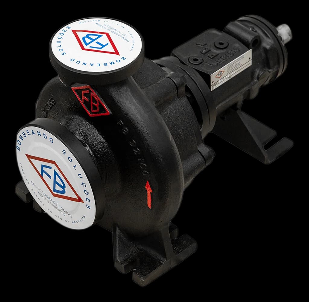
Drawing and dimensions for FBOT 50-160
Figure 4 of manual MTEC-16/00 beside this model’s dimensions from Table 5, in millimetres and grouped as in the manual.
- Suction
- DN 80
- Discharge
- DN 50
- Bearing frame
- 3
- Identification
- FBOT-50-160 · Standard
Model dimensions
MTEC-16/00 · Table 5 · mmPump
- DN1 · Suction
- 80
- DN2 · Discharge
- 50
- a
- 100
- f
- 360
- h1
- 160
- h2
- 180
Foot
- b
- 50
- g1
- 15
- g2
- 6.35
- l1
- 30
- m1
- 100
- m2
- 70
- m3
- 65
- n1
- 265
- n2
- 212
- n3
- 160
- n4
- 110
- s1
- 14
- s2
- 14
- V
- 100
- W
- 260
Shaft end
- d1 m6
- 24
- l
- 50
- t
- 26.9
- u
- 8
- x
- 100
Performance and discharge pressure
Preliminary selection charts and Figure 1 of the manual, converted to light lines from the originals. They are series selection maps, not individual curves for this model.
Preliminary selection chart · 1,750 rpm
Preliminary selection chart · 3,500 rpm
These maps are not individual performance curves. On their own, they do not specify power, required NPSH or an impeller for your duty point. Series maxima do not describe one simultaneous operating point either.
The compact catalogue and manual have different coverage. For large-capacity ranges, also consult the manual charts; a code’s absence from these two images does not indicate discontinuation.
Maximum discharge pressure × temperature
MTEC-16/00 · Figure 1 · p.5Maximum discharge pressure depends on temperature. Refer to Figure 1 on page 5 of manual MTEC-16/00 and confirm the limit for the configuration and duty point with engineering. Do not substitute interpolated values for the original chart when selecting the equipment.
Limits and model construction
Table 1 and items 2 to 5 of manual MTEC-16/00, with the bearings of this model’s bearing frame. Series maxima do not describe one simultaneous operating point.
- Maximum temperature
- 350 °C
- Maximum speed
- 3,500 rpm
- Maximum suction pressure
- 10 bar
- Direction of rotation
- Clockwise, viewed from drive end
- Impeller type
- Closed radial, single suction
- Hydrostatic test pressure
- 1.5 × operating pressure
- Bearing frame 3 — bearings
- 6306 C4 / 6306 ZZ C4 WT
- Bearing lubrication
- Oil; the shielded bearing is grease-lubricated (item 2.4)
- Graphite fibre packing
- 5.5 mm · 3 pieces (part 461)
- Single mechanical seal
- Ø32 / Ø42 mm
- Flanges
- ANSI B16.42 150 lbs or DIN EN 1092-2 PN16 (optional)
MTEC-16/00 · Table 1 (p.4) · items 2.2 to 2.4 (p.5) · item 4 (p.6). Review series limits and the manual before defining the equipment. Catalogue maxima do not describe a single operating point.
Standard model — default FBOT configuration
FBOT-50-160This model follows the standard configuration identified in the FBOT catalogue. The manual describes a spiral casing, closed radial impeller and dual sealing. Check suction pressure and maximum discharge pressure at operating temperature against Figure 1; also validate flow, head and start-up conditions with engineering.
Impeller materials and peripheral speed
MTEC-16/00 · item 5 · p.6| Value | m/s |
|---|---|
| Cast Iron | 40 |
| Ductile Iron | 60 |
| Carbon Steel | 60 |
| Stainless Steels | 80 |
Motor power reserve
MTEC-16/00 · Table 2 · p.5| Absorbed power (CV) | Motor power reserve |
|---|---|
| up to 2 | ≈ 20% (minimum 1,5 cv) |
| up to 20 | ≈ 15% |
| above 20 | ≈ 10% |
Connections and accessories
MTEC-16/00 · item 4 · p.6 · Table 4 · p.9- ANSI B16.42 150lbs (standard)
- DIN EN 1092-2 PN16 (optional)
- Electric motor (driver)
- Flexible coupling with or without spacer (FB standard or other manufacturers)
- Coupling guard in carbon steel or anti-spark material
- Steel "U"-shaped plate base
| Connection | Designation | Size |
|---|---|---|
| D1 | Support drain | ¼" BSP |
| D2 | Mechanical seal leakage indicator | ¼" BSP |
| FF | Oil supply | ¼" BSP |
| V | Vent | ¼" BSP |
Built for thermal oil
Manual MTEC-16/00 describes the series construction, sealing arrangement and pump selection conditions.
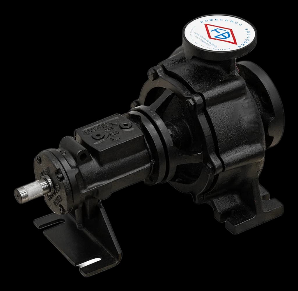
Dual sealing
Sealing with graphite packing and a mechanical seal. The configuration and maintenance instructions must match the supplied equipment.
Back pull-out maintenance
Back-pull-out construction — allows bearing frame removal without disconnecting/misaligning piping. Simplifies maintenance.
Closed radial impeller
Closed radial impeller, single suction.
Casing and bearing frame
Spiral-shaped body, cast in single piece without feet. Bearing frame with 2 bearings — one oil-submerged, other shielded and grease-lubricated.
Manual MTEC-16/00 (§2.3) describes the seal immersed in bearing housing oil; the current catalogue (page 2) refers to the thermal oil itself. Confirm your pump configuration and the corresponding lubrication and maintenance instructions with engineering.
Circulating thermal oil
FBOT is intended for organic thermal oil circuits. Specify the oil and temperature and confirm component compatibility; the fluid must not contain abrasive particles.
Explore series applications and selection criteriaSectional view and parts list
Figure 2 of manual MTEC-16/00 with the Table 3 parts list, numbered according to DIN EN 24250, with the quantities given in the manual.
| Part no. | Description | Qty |
|---|---|---|
| 102 | Casing — Spiral Body | 1 |
| 163 | Pressure Cover | 1 |
| 183 | Support Foot | 1 |
| 210 | Shaft | 1 |
| 230 | Impeller | 1 |
| 321.01 | Radial Ball Bearing | 1 |
| 321.02 | Shielded Radial Ball Bearing, grease-lubricated | 1 |
| 330 | Bearing Frame | 1 |
| 360 | Bearing Cover | 1 |
| 400.01 | Flat Gasket — casing / pressure cover | 1 |
| 400.03 | Flat Gasket — bearing cover / bearing frame | 1 |
| 411 | Sealing Washer — FF, V and D1 connections | 3 |
| 433 | Mechanical Seal | 1 |
| 461 | Graphite Packing | 3 |
| 502 | Casing Wear Ring | 1 |
| 503 | Impeller Wear Ring | 1 |
| Part no. | Description | Qty |
|---|---|---|
| 550 | Support Cover | 1 |
| 551.01 | Spacer Washer — packing | 1 |
| 551.04 | Spacer Washer — bearing | 2 |
| 710 | Pipe | 1 |
| 901.01 | Hexagon Head Bolt — pressure cover / casing | 6 |
| 901.03 | Hexagon Head Bolt — bearing frame / casing | 4 |
| 901.13 | Hexagon Head Bolt — support foot / bearing frame | 1 |
| 903 | Plug — FF, V and D1 connections | 3 |
| 914 | Hexagon Socket Screw — bearing cover | 4 |
| 922 | Impeller Nut | 1 |
| 932.01 | Retaining Ring — packing | 1 |
| 932.04 | Retaining Ring — bearings | 2 |
| 936 | Lock Washer | 1 |
| 940.1 | Key — impeller | 1 |
| 940.2 | Key — coupling | 1 |
| 970 | Nameplate | 1 |
Part numbers according to DIN EN 24250 (Table 3 of manual MTEC-16/00). When requesting spare parts, provide the complete model code and the part number.
Documentation FBOT
The product catalogue and technical manual are in Portuguese. Review the available drawings and confirm the supplied configuration and dimensions in the quotation.
Technical manual · MTEC-16/00
Manual MTEC-16/00 describes the series construction, sealing arrangement and pump selection conditions.
Product catalogues

These catalogues complement the technical manuals. For sizing and operating limits, consult the specific documentation and engineering team.
Questions about FBOT 50-160
Technical and commercial information to prepare your selection.
What are the nominal flange dimensions of the FBOT 50-160?
The FBOT 50-160 has suction flange DN80mm and discharge flange DN50mm, per Table 5 of the FBOT Technical Manual. Available flanges: ANSI B16.42 150lbs (standard) or DIN EN 1092-2 PN16 (optional).
What does the FBOT 50-160 designation mean?
The designation follows the FB standard: "FBOT 50-160" where 50 is the discharge flange nominal diameter in mm and 160 is the impeller nominal diameter in mm.
What is the maximum operating temperature of the FBOT 50-160?
Manual MTEC-16/00 states 350 °C as the series temperature limit. For FBOT 50-160, confirm the fluid, configuration and duty point. Maximum discharge pressure depends on temperature: refer to Figure 1 on page 5 and ask engineering to confirm the limit applicable to the supplied equipment.
What is the sealing system of the FBOT 50-160?
Sealing with graphite packing and a mechanical seal. The configuration and maintenance instructions must match the supplied equipment. Manual MTEC-16/00 (§2.3) describes the seal immersed in bearing housing oil; the current catalogue (page 2) refers to the thermal oil itself. Confirm your pump configuration and the corresponding lubrication and maintenance instructions with engineering.
What bearings does the FBOT 50-160 use?
The FBOT 50-160 uses two ball bearings in bearing frame 3: one runs submerged in oil and the other is shielded and grease-lubricated, per Section 2.4 and Tables 1 and 3 of the FBOT Technical Manual.
Does the FBOT 50-160 have back-pull-out construction?
Yes. All FBOT pumps, including the 50-160, have back-pull-out construction — the bearing frame can be removed from the casing without disconnecting/misaligning the piping. This simplifies assembly, disassembly and maintenance.
What impeller materials are available for the FBOT 50-160?
Available materials with peripheral speed limits (manual Section 5): Cast Iron up to 40 m/s, Ductile Iron up to 60 m/s, Carbon Steel up to 60 m/s, Stainless Steels up to 80 m/s. The choice depends on thermal oil and temperature conditions. Consult FB engineering for technical recommendation.
What auxiliary connections does the FBOT 50-160 have?
The FBOT 50-160 has 4 auxiliary connections of ¼" BSP (manual Table 4): D1 (support drain), D2 (mechanical seal leakage indicator), FF (oil supply) and V (vent). They allow monitoring and maintenance of the sealing system.
What motor power reserve is recommended for the FBOT 50-160?
Manual Table 2 defines motor power reserve: up to 2cv of required pump power → ~20% (minimum 1.5cv); up to 20cv → ~15%; above 20cv → ~10%. Important to avoid overload operation and extend motor service life.
What is the rotation direction of the FBOT 50-160?
Clockwise, viewed from the drive end (manual Table 1). Maximum rotation is 3500 rpm. For operation selection at 1750 rpm or 3500 rpm, consult the characteristic curves (manual Section 1). Hydrostatic test is performed at 1.5 × operating pressure.
Which technical standards does the FBOT 50-160 comply with?
FBOT manual MTEC-16/00 cites ANSI B16.42 150lbs or DIN EN 1092-2 PN16 flanges, part numbering according to DIN EN 24250 and hydrostatic testing at 1.5 times operating pressure. For FBOT 50-160, confirm the supplied flange and configuration in the quotation. If the project requires ASME B73.1, balancing or a specific test, request the corresponding engineering documentation.
Your circuit. An engineering selection.
Share the available process data. With it, FB Bombas engineering checks the duty point on the 1,750 or 3,500 rpm curve, the discharge pressure allowed at the operating temperature, the impeller material and the motor power reserve, and specifies the model, configuration and documentation for supply.
Information to provide
- Thermal oil, temperature and fluid properties.
- Flow, total head and intended speed.
- Suction pressure, available NPSH and start-up conditions.
- Flange standard (ANSI B16.42 150 lbs or DIN EN 1092-2 PN16) and intended drive.
- For a replacement: complete code, nameplate data and drawing of the installed pump.
Nearby models FBOT
Same DN or adjacent discharge diameter. Compare the technical data before considering a replacement.
Continue your assessment
Explore the full family, documentation and content related to your circuit.